

| ETERNUS SF Storage Cruiser User's Guide 13.2 - Solaris (TM) Operating System / Linux / Microsoft(R) Windows(R) - |
|
Contents
Index
|
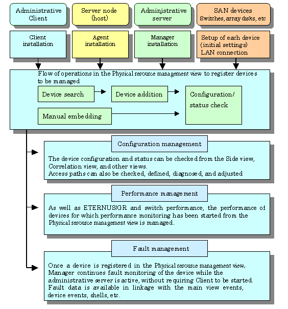
This chapter provides settings and notes required for devices to be managed.
Whether building a new storage system or using this software product for an existing storage system, start the environment setup and operation according to the procedure indicated in the figure shown below. Software can be installed and set up on individual devices in any sequence.
Note that once this software product is installed and devices to be managed are registered, fault monitoring and fault recovery are performed for the registered devices while the administrative server is active, without having to start the Client window (GUI window). Also, performance information is stored for devices subject to performance management.
Two methods are used for managing Solaris OS server nodes: one method installs Agent on the host, and the other does not.
When Agent is installed, the following functions are available: the configuration data is automatically loaded from the server node; the system fault and status is monitored for Fujitsu's multipath disk control mechanism, mirror disks, and file systems; the line drawing for FC connection is performed; the access path settings are configured including server node HBA binding (storage affinity). Without Agent installed, the host can still be registered manually but status reading/access path setting/fault monitoring is disabled.
For information about products that can be monitored by Agent, see "10.5 Server Node Middleware that can be Managed".".

The following limitations apply if Solaris OS server nodes are managed using the Agent:
HBA WWNN and PID binding (storage affinity) settings are not supported.
The access path is managed automatically in this product using WWPN (World Wide Port Name). Accordingly, if WWNN (World Wide Node Name), PID, or TID binding has already been set in the server node HBA (host bus adapter), the settings must be changed to WWPN binding before the device is registered in this product. Server nodes that are used to perform WWNN, PID, or TID binding cannot be registered in this product.
If device files of more than one controller number are generated
If more than one device driver type is used to access storage of a different type from a single HBA, device files for at least 2 controller numbers may be generated for the single HBA. This product does not support this status.
If there is a problem with information gathering or display, manage the server nodes using the manual embedding function. (For details about the manual embedding function, refer to "5.2.6 Registering a Manually Embedded Device".)
The methods used to manage Solaris OS server nodes installed in SUN-made HBAs and Fujitsu-made HBAs using Agents are different. These differences are shown in the table below.
|
Function |
Fujitsu-made HBAs |
SUN-made HBAs |
|
Access path settings |
Specify the target number and LUN when the access path is set. |
Settings are not configured in the settings file, so enter the default values for the target number and LUN when the access path is set. The command for enabling recognition of the LUN must also be entered. |
|
Access path color |
If the LUN is recognized, the color changes from Blue to Green. |
This is always blue in the normal status. LUN needs to be confirmed by the operating system command. When the status of the multipath is not reflected in the Access path color, the operating system command needs to be used to check this.
|
|
Access path display in FC-AL environments |
This can be displayed. |
This cannot be displayed. |
|
Physical connection line display in FC-AL environments |
This can be displayed. |
This cannot be displayed. |
|
Main view HBAs |
This is displayed as the logic HBA number before recognition of the LUN, and in Cx format after recognition of the LUN. |
The logical HBA number is always displayed. |
|
Beacon blinking |
Possible. |
Not possible (the menu cannot be selected). |
|
Main view server multipath display |
This is displayed when there is a multipath environment. The path can also be displayed by selecting the multipath instance name. |
Information on the multipath driver device is not displayed. Therefore, multipath driver's path information cannot be displayed. |
|
Main view server property multipath information |
This is displayed when there is a multipath environment. |
This is not displayed (only the option name is displayed). |
|
Main view HBA property connection admission WWPN, target number, and LUN information |
This is displayed. |
This is not displayed (the connection admission WWPN is displayed if the access path is set in a fabric environment). |
|
Element display except for Relationship Management window HBA nodes and HBA ports |
Raw devices, multipath devices, and file systems (ufs, zfs) are displayed. |
A file system (ufs,zfs,QFS/SAM-QFS/SAM-FS) will be displayed. A multipath driver device (MPxIO) is displayed. |
|
Relationship Management window HBA port property connection admission WWPN, target number, and LUN information |
This is displayed. |
This is not displayed (the connection admission WWPN is displayed if the access path is set in a fabric environment). |
|
Relationship Management window path display |
This is displayed. |
A path within the server unit will be supported. It will be displayed by tracing back the information connected to the multipath drive device. |
|
Multipath path monitoring |
Path display, multipath path monitoring, and HBA port status display are possible. |
Multipath path can be monitored. It is possible to detect an error because HBA port status such as disconnection of a cable is displayed |
|
Multipath path display |
It is possible to show a light blue color on the information of the access path and the storage information area, by selecting and clicking a multipath device file name on the server icon in the resource control window. |
In the relationship management window, the path from a multipath device to the HBA port can be displayed. |
To manage the HBAs that are installed at Solaris OS server nodes, the SNIA HBA API library that an HBA vendor distributes must be installed.
When using PW008FC2A,PW008FC2-G,PW008FC3,GP7B8FC1A,GP7B8FC1-G,GP7B8FC1
Install the SNIA HBA API library by installing a PW008FC2A,PW008FC2-G,PW008FC3,GP7B8FC1A,GP7B8FC1-G,GP7B8FC1 driver (FUJITSU PCI Fibre Channel 2.2.1 or 3.0)
When FUJITSU PCI Fibre Channel 2.2.1 is installed, it must be patched (by 912069-17 or later). Note that FUJITSU PCI Fibre Channel 2.2 cannot be used any more.
Emulex Corporation LP9000/9002S/9002L/9802/10000
Install HBAnyware (SNIA HBA API) according to the instructions in the driver's handbook.
Using SE0X7F11F or SE0X7F12F
After installing the SE0X7F11F or SE0X7F12F driver (FUJITSU PCI Fibre Channel 4.0 or higher), the SNIA HBA API library must be changed according to the following procedure.
Change the link from "/usr/lib/libfchba.so" to "/opt/FJSVpfca/sbin/libfchba.so" to "/opt/FJSVpfca/sbin/libfchba1.so".
# rm /usr/lib/libfchba.so
# ln -s /opt/FJSVpfca/lib/libfchba1.so /usr/lib/libfchba.so
Reboot.
# /usr/sbin/shutdown -y -i6 -g0
Using XSEFC401AF or XSEFC402AF
The SNIA HBA API library is included in the driver that is handled in the OS, therefore it has no settings.
When using SG-XPCI1FC-QF2,SG-XPCI2FC-QF2,SG-XPCI1FC-QL2,SG-XPCI2FC-QF2-Z
There is no need to set up SNIA HBA API library, as it is included in the driver which is bundled with the operating system.
N port setting is needed on the side of HBA when connecting with the Fibre Channel switch. The method of setting the port of HBA as N port depends on the HBA type. Each method for setting is shown below.
PW008FC2A,PW008FC2-G,PW008FC3,GP7B8FC1A,GP7B8FC1-G,GP7B8FC1,SE0X7F11F, SE0X7F12F driver
Describe the following port type in the /kernel/drv/fjpfca.conf file in each instance name of fjpfca(Adapter).
port= "fjpfca0:nport", "fjpfca1:nport"; |
Emulex Driver (LPFC/LPFS driver)
The topology parameter of /kernel/drv/lpfc.conf or lpfs.conf file is set to 2 as follows:
# topology: link topology for initializing the Fibre Channel connection. # 0 = attempt loop mode, if it fails attempt point-to-point mode # 2 = attempt point-to-point mode only # 4 = attempt loop mode only # 6 = attempt point-to-point mode, if it fails attempt loop mode # Set point-to-point mode if you want to run as an N_Port. # Set loop mode if you want to run as an NL_Port. topology=2; |
XSEFC401AF or XSEFC402AF driver
Specify "2" for the emlxsX-topology parameter in the /kernel/drv/emlxs.conf file.
# # +++ Fibre Channel specific parameters +++ # # topology: link topology for initializing the Fibre Channel connection. # # 0 = attempt loop mode, if it fails attempt point-to-point mode # 2 = attempt point-to-point mode only # 4 = attempt loop mode only # 6 = attempt point-to-point mode, if it fails attempt loop mode # # Set point-to-point mode if you want to run as an N_Port. # Set loop mode if you want to run as an NL_Port. # # Range: Min:0 Max:6 Default:0 # emlxs0-topology=2; emlxs1-topology=2; |
N port settings for SG-XPCI1FC-QF2,SG-XPCI2FC-QF2,SG-XPCI1FC-QL2,SG-XPCI2FC-QF2-Zdriver are not required.
Note that database monitoring requires the following actions to be taken in advance:
Registering user information
Execute the defusr command, and register the user information necessary for database monitoring. For information about the defusr command, see "C.5.1.1 User information setting command (defusr)".
For information about particulars specified in the defusr command, see descriptions of monitoring each database.
Monitoring for Symfoware
Define the environment variables necessary for database access (e.g., LD_LIBRARY_PATH) in the sstorageagt.conf file. For information about the sstorageagt.conf file, see "D.8 sstorageagt.conf Parameter". For information about the necessary environment variables, refer to the appropriate Symfoware manual. In order to use multiple RDBs, a Symfoware statement must be defined in the Correlation.ini parameter. For information about the Correlation.ini parameter, see "D.7 Correlation.ini Parameter". The registration of the user information by the defusr command is unnecessary.
Monitoring for Oracle
The JDBC driver is used to access Oracle. In the sstorageagt.conf file, define an environment for using the JDBC driver; and, using an Oracle statement in the Correlation.ini parameter, specify the number of the port used for access. For information about the sstorageagt.conf file, see "D.8 sstorageagt.conf Parameter". For information about the Oracle statement in the Correlation.ini parameter, see "D.7 Correlation.ini Parameter". For information about definitions necessary for the JDBC driver environment, refer to the appropriate Oracle manual.
The key name of the defusr command must be assigned the instance name subject to configuration management.
This software product provides two methods for managing Windows hosts: one method installs Agent on the host, and the other does not.
When Agent is installed, the following functions can be implemented: the configuration data is automatically loaded from the server node; the line drawing for FC connection is performed; the system fault and status is monitored for Fujitsu's multipath disk control mechanism. Without Agent installed, the host can still be registered manually but status reading/access path setting/fault monitoring is disabled.
For information about the products that can be observed by Agent, see "10.5 Server Node Middleware that can be Managed".
If the PG-FC105 driver is reinstalled, or the PG-FC105 adapter and other option cards are added , reduced , or replaced, there may be entries for which "(Disconnected)" is displayed for "Emulex Configuration Tool". In this case, delete the entry according to the procedure shown below. If this entry is not deleted, invalid information may be displayed in the client window.
Procedure to delete the entry:
Click [Start] > [Run].
Enter "elxcfg" and then click the <OK> button.
The Emulex Configuration Tool starts up.
The list of PG-FC105s loaded in the server nodes is displayed in Available Adapters.
<Example of the list that is displayed>
Emulex LP-9000 Adapter, Bus 1 Slot 7 (Present)
Emulex LP-9000 Adapter, Bus 1 Slot 8 (Present)
Select the entry for which "(Disconnected)" is displayed, click the [File] menu and select [Remove].
To manage the HBAs that are installed in Windows server nodes, the SNIA HBA API library that an HBA vendor distributes must be installed.
When PG-FC105 (Driver v5-2.13a4) is used
By installing a PG-FC105 driver, the SNIA HBA API library is installed.
PG-FC105 (other than Driver v5-2.13a4), PG-FC106, PG-FC107, PG-FC201, PG-FC202, PG-FCD201, Emulex Corporation LP9000, 9002L, 9802, 1050, 1050Ex
Install HBAnyware (SNIA HBA API) according to the user's guide for the HBA card or the driver's handbook.
If PG-FC202 or PG-FCD201 is used, change agent-installation-directory \Agent\bin\HBAAPI.dll to another name (for example, HBAAPI.dll.bak).
If the agent-installation-directory\Agent\bin\HBAAPI.dll does not exist, file name change is not necessary.
PG-FCD101, PG-FCD102, QLA2340
Copy agent-installation-directory\Agent\lib\HBAAPI.dll to agent-installation-directory\Agent\bin\HBAAPI.dll.
If the copy destination directory already contains the same file, the file need not be copied.
MC-08FC11, MC-08FC31, MC-08FC41, MC-08FC51, MC-08FC61, or MC-08FC71
Install HBAnyware (SNIA HBA API) by referring to the operation manual of the HBA card or the driver manual.
To connect Emulex Corporation LP7000, 8000, 9000, 9002L, 9802, 1050, 1050Ex, to a Fibre Channel switch, N-port settings are required on the HBA side.
To make up a SAN by connecting Emulex Corporation LP7000, 8000, 9000, 9002L, 9802, 1050, 1050Ex to the fibre channel switch, use the driver parameter in the registry to indicate explicitly that the topology is an N-port. The following indicates the procedure for setting the topology in the driver parameter:
Open the registry editor.
Select [Start]-[Run...] from the task bar, and then execute the following:
regedit.exe
Open the keyword of the following registry key, and then set the Topology value to 1:
HKEY_LOCAL_MACHINE\
System\
   CurrentControlSet\
    Services\
     lpxnds\
      Parameters\
         Device\
         "DriverParameter"      Topology=1
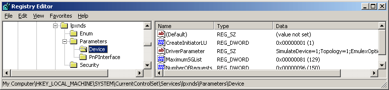
The DriverParameter value depends on the version of the driver used. The Topology word may not exist depending on the driver version. In this event, the Topology word must be added. For details, see the readme file supplied with the driver or contact the HBA vendor.
If the system accommodates more than one Emulex HBA and you want to connect them to Fibre Channel using different topologies, follow the above procedure for each HBA. For details, see the readme file supplied with the driver or contact the HBA vendor.
The procedure involves changing the registry contents. Take particular care when carrying out the procedure because, if any part of the registry becomes corrupted as a result of an operation mistake or an operation that is not in the procedure, restarting the Windows system may not be possible.
Note that database monitoring requires the following actions to be taken in advance:
Registering user information
Execute the defusr command, and register the user information necessary for database monitoring. For information about the defusr command, see "C.6.1.1 User information setting command (defusr)". For information about particulars specified in the defusr command, see descriptions of monitoring each database.
Monitoring Symfoware
Define the environment variables necessary for database access (for example, PATH) in the sstorageagt.conf file. For information about the sstorageagt.conf file, see "D.8 sstorageagt.conf Parameter". For information about the necessary environment variables, refer to the Symfoware manual. In order to use multiple RDBs, a Symfoware statement must be defined in the Correlation.ini parameter. For information about the Correlation.ini parameter, see "D.7 Correlation.ini Parameter". The registration of the user information by the defusr command is unnecessary.
Monitoring Oracle
The JDBC driver is used to access Oracle. In the sstorageagt.conf file, define an environment for using the JDBC driver, and specify the port number used for access in an Oracle statement in the Correlation.ini parameter. For information about the sstorageagt.conf file, see "D.8 sstorageagt.conf Parameter". For information about the Oracle statement in the Correlation.ini parameter, see "D.7 Correlation.ini Parameter". For information about definitions necessary for configuring the JDBC driver, refer to the Oracle manual. The key name of the defusr command must be assigned the instance name subject to configuration management.
Monitoring SQL Server
To access an instance with a name or to log in with SQL Server authentication, an SQLServer statement must be defined in the Correlation.ini parameter. For information about the Correlation.ini parameter, see "D.7 Correlation.ini Parameter". Although any key name can be specified for the defusr command, it must be identical with the key name described in the SQLServer statement in the Correlation.ini parameter.
This software product provides Linux server nodes with two management methods. In one method Agent is installed and in the other method Agent is not installed.
When Agent is installed, automatic import of the server node configuration from Manager, FC connection plot, and fault and status monitoring of the Fujitsu's multipath disk control mechanism become available. Without Agent installed, the host can still be registered manually but status reading/access path setting/fault monitoring is disabled.
For information about the products that can be observed by Agent, see "10.5 Server Node Middleware that can be Managed".
It is necessary to install the HBA API library that the HBA vender distributes to manage HBA installed in the Linux server node.
PG-FC105, PG-FC106, PG-FC107, PG-FC201, PG-FC202, PG-FCD201
Execute the next item of "Checking whether the HBA API library has been installed".
Driver version is V1.23a-0/V420q-1
Install the SNIA HBA API common library (supporting Common HBA API Version 2.18) as follows.
If /usr/lib/libHBAAPI.so file exists, save it.
Copy /opt/FJSVssage/lib/libHBAAPI.so in /usr/lib/ or create the symbolic link as follows:
|
# ln -s /opt/FJSVssage/lib/libHBAAPI.so /usr/lib/libHBAAPI.so |
As for libemulexhbaapi.so(SNIA HBA API vendor library), contact your Fujitsu systems engineer (SE).
If the driver version is not V1.23a-0 or V4.20q-1
As for HBA API library, contact your Fujitsu systems engineer (SE).
Checking whether the HBA API library has been installed.
Check whether the following two conditions are met to determine the installation status. If both the conditions are met, the HBA API library has been installed.
All of the following files exist.
- /usr/lib/libHBAAPI.so
- /usr/lib/libemulexhbaapi.so
- /etc/hba.conf
Executing the following command results in an integer that is 1 or larger.
(The command is one line.)
|
egrep -c [^[:blank:]]+[[:blank:]]+/usr/lib/libemulexhbaapi.so /etc/hba.conf |
PG-FCD101, PG-FCD102
Execute the next item of "Checking whether the HBA API library has been installed". Install SNIA HBA API common library which corresponds to this software product (corresponding to Common HBA API Version 2.18) as follows.
If /usr/lib/libHBAAPI.so file exists, save it.
Copy /opt/FJSVssagt/lib/libHBAAPI.so in /usr/lib/ or create the symbolic link as follows:
|
# ln -s /opt/FJSVssage/lib/libHBAAPI.so /usr/lib/libHBAAPI.so |
As for libqlsdm.so(SNIA HBA API vendor library), contact your Fujitsu systems engineer (SE).
Checking whether the HBA API library has been installed.
Check whether the following two conditions are met to determine the installation status. If both the conditions are met, the HBA API library has been installed.
All of the following files exist.
- /usr/lib/libHBAAPI.so
- /usr/lib/libqlsdm.so
- /etc/hba.conf
Executing the following command results in an integer that is 1 or larger.
(The command is one line.)
|
egrep -c [^[:blank:]]+[[:blank:]]+/usr/lib/libqlsdm.so /etc/hba.conf |
MC-08FC11, MC-08FC31, MC-08FC41, MC-08FC51, MC-08FC61, MC-08FC71
Install HBAnyware (SNIA HBA API) by referring to the operation manual of the HBA card or the driver manual.

The udev device is a Linux function that always assigns a fixed device name, even if the hardware configuration is changed.
It assigns a device name that starts with "/dev/disk", unlike for existing device names, such as "/dev/sda".
"/dev/disk/by-path/xxxxxxxx" xxxxxxxx is information generated from the disk location information
"/dev/disk/by-id/yyyyyyyy" yyyyyyyy is information generated from the disk ID information
In the following explanations, device names that start with "/dev/disk/by-path" are shown as "by-path", and device names that start with "/dev/disk/by-id" are shown as "by-id". Existing device names, such as "/dev/sda", are shown as compatible device names.
If the Linux udev function is used for devices monitored using ESC, use "by-id".
"by-id" is a symbolic link to "/dev/sd?name", therefore the relationship for "by-id" and the compatible device name displayed in this product can be checked by using the "ls -l /dev/disk/by-id" command.
Example: The method shown below checks "by-id" for "/dev/sdb"
|
# ls -l /dev/disk/by-id/ Total 0 lrwxrwxrwx 1 root root 9 April 3 21:28 scsi-1FUJITSU_300000690000 -> ../../sdb lrwxrwxrwx 1 root root 10 April 3 21:28 scsi-1FUJITSU_300000690000-part1 -> ../../sdb1 lrwxrwxrwx 1 root root 10 April 3 21:28 scsi-1FUJITSU_300000690000-part2 -> ../../sdb2 lrwxrwxrwx 1 root root 10 April 3 21:28 scsi-1FUJITSU_300000690000-part3 -> ../../sdb3 lrwxrwxrwx 1 root root 10 April 3 21:28 scsi-1FUJITSU_300000690000-part7 -> ../../sdb7 lrwxrwxrwx 1 root root 9 April 3 21:28 scsi-1FUJITSU_300000690001 -> ../../sdc lrwxrwxrwx 1 root root 10 April 3 21:28 scsi-1FUJITSU_300000690001-part1 -> ../../sdc1 lrwxrwxrwx 1 root root 10 April 3 21:28 scsi-1FUJITSU_300000690001-part2 -> ../../sdc2 lrwxrwxrwx 1 root root 10 April 3 21:28 scsi-1FUJITSU_300000690001-part3 -> ../../sdc3 lrwxrwxrwx 1 root root 10 April 3 21:28 scsi-1FUJITSU_300000690001-part7 -> ../../sdc7 lrwxrwxrwx 1 root root 9 April 3 21:28 scsi-1FUJITSU_300000690002 -> ../../sdd lrwxrwxrwx 1 root root 10 April 3 21:28 scsi-1FUJITSU_300000690002-part1 -> ../../sdd1 lrwxrwxrwx 1 root root 10 April 3 21:28 scsi-1FUJITSU_300000690002-part2 -> ../../sdd2 lrwxrwxrwx 1 root root 10 April 3 21:28 scsi-1FUJITSU_300000690002-part3 -> ../../sdd3 lrwxrwxrwx 1 root root 10 April 3 21:28 scsi-1FUJITSU_300000690002-part7 -> ../../sdd7 |
Accordingly, it is possible to determine that "by-id" of "/dev/sdb" is "/dev/disk/by-id/scsi-1FUJITSU_300000690000".
"by-path" for the device that is connected to the Fibre Channel switch may change, therefore specify "by-id".
Linux device nodes are displayed as "compatible device name sd?" in this product. "by-id" and "by-path" are not displayed. Check the relationship using the command as shown above.
To monitor databases, the following must have been executed:
Registering user information
Use the defusr command to register the user information that is required to monitor databases. Refer to C.7.1.1 User information setting command (defusr) for details of the defusr command. For the contents to be specified in the defusr command, refer to the explanation for monitoring each database.
Monitoring Symfoware
Define in the sstorageagt.conf file the environment variables (such as LD_LIBRARY_PATH) that are required to access databases. Refer to "D.8 sstorageagt.conf Parameter". For the required environment variables, refer to the Symfoware manuals. For multiple-RDB operation, the Symfoware statement for the Correlation.ini parameter must be specified. Refer to "D.7 Correlation.ini Parameter". Note that user information registration by the defusr command is not required.
Monitoring Oracle
The JDBC driver is used to access Oracle. Use the sstorageagt.conf file to define the environment for using the JDBC driver and define the port number for accessing Oracle in the Oracle statement for the correlation.ini parameter.
Refer to "D.8 sstorageagt.conf Parameter" and "D.7 Correlation.ini Parameter" for details of the Oracle statement for the correlation.ini parameter. For the required JDBC driver environment definitions, refer to the Oracle manuals. As the defusr command key name, specify an instance name subject to configuration management.
This software product provides two methods for managing the HP-UX server node. In one method, Agent is installed on the node, in the other, it isn't.
Installing Agent enables automatic loading of server node configuration data from the manager and displaying FC connections in the form of lines. It also enables system fault monitoring and status monitoring for PV-LINK (a function of LVM) from the manager. When Agent is not installed, nodes can still be registered manually, but status inquiry, setting access paths, and fault monitoring cannot be performed.
See "10.5 Server Node Middleware that can be Managed" for information on products that can be monitored by Agent.
To manage the HBA mounted on an HP-UX server node, the HBA API library must be installed. When in doubt, contact your HBA sales representative.
This product software also provides a method for manually managing server nodes that are not supported by Agent or Solaris OS/Windows/Linux/HP-UX environments in which Agent is not installed.
Status inquiry or automatic reading of configuration data from a device cannot be performed, but the configuration can be changed by displaying the devices on the screen and manually editing the configuration.
For information on the procedure for registering a managed server without Agent, see "5.2.6 Registering a Manually Embedded Device".
This software product can manage server nodes on which Softek Storage Cruiser is installed. It can manage the all versions of the Agent.
For information on models which Softek Storage Cruiser Agentsupport, see "1.5.1 Hardware requirements" in the "Softek Storage Cruiser User's Guide".
For information on the procedure for registering a serve node, see "5.2.1 Device search".
The registered server node is managed as managed server node only for monitoring, and device icon is displayed in the GUI window.
The functions shown below can be used for server nodes registered in this product. For information about middleware products that can be managed using correlation window, refer to "1.5.2 Software requirements" in the "Softek Storage Cruiser User's Guide" for the appropriate version.
Resource configuration management
Physical resource view
Correlation window
Access path management
This software product installs agents on the host operating system for VMware server node and manages them.
This software product cannot manage the guest operating system for VMware server nod
This product is managed by the Agent installed on the VMware server node.
The VMware server node is treated the same as the Linux server node in the following product manuals.
ETERNUS SF Storage Cruiser User's Guide
ETERNUS SF Storage Cruiser Message Guide
ETERNUS SF Storage Cruiser Event Guide
Refer to "4.1.3 Linux server node (host)" for details of environmental settings.
This software product operates both on the VMware server node and the Linux server node. However controllable middleware differs between them. For details, refer to "10.5 Server Node Middleware that can be Managed".
The settings that must be directly defined on the device side before this software product manages these Fibre Channel switches are explained below. For details, refer to the manual supplied with the respective device.
IP address, subnet mask, and gateway address (required)
Define the IP address, subnet mask, and gateway address for a LAN. If the Fibre Channel switch is equipped with an operation panel, these settings can be defined from the operation panel. If the Fibre Channel switch is equipped with a serial port, define them by issuing the ipAddrSet command via the serial port.
User name and password for Fibre Channel switch control
For Fibre Channel switch control, this software product is used to log in using telnet to the device. Control requires a user name and password of the administrator security level. The factory default settings of user name and password are "admin" and "password", respectively.
If the password has been changed on the device side, this product recognizes the change and displays the device icon as a warning when [Refresh] is selected. Also, the monitoring status of the device becomes "Invalid password".
In order for the setting to match the changed device setting, select the device icon in the domain view of the physical resource view, and select [Device]-[Change account for device management] from the main menu.
For some types of devices, the change of the password on the device side cannot be recognized automatically, and the status does not become "Invalid password". Click [Device] > [Change account for device management] in the main menu for these devices as well.
When connected to a cascade, some types of devices cannot automatically recognize the changed password; therefore the status doesn't become "Invalid password." In this case, delete the device and register it again. Refer to "5.2 Creating/Registering device" for details on deleting and registering devices.
Domain name
A domain name is a unique name defined for a Fibre Channel switch in a SAN. Such names are necessary for a cascade connection of multiple Fibre Channel switches. Since domain names are automatically defined by firmware built into the individual Fibre Channel switches, the name need not be considered during definition and management of access paths using this software product.
However, the domain names are important elements in manual port zoning. In such cases, make sure that no identical value is set for any two Fibre Channel switches in the cascade connection. If a Fibre Channel switch is equipped with an operation panel, a domain name can be set from the operation panel. If a Fibre Channel switch is equipped with a serial port or if network settings are defined for the Fibre Channel switch, log in to the switch, and set a domain name by executing the configure command.
SysName (recommended)
Register a switch name for Fibre Channel switch control. This software product uses this switch name as SysName. SysName should be a name that is not identical to any other name registered with this software product. If the Fibre Channel switch is equipped with an operation panel, a switch name can be set from the operation panel. If the Fibre Channel switch is equipped with a serial port or if the network settings are defined for the Fibre Channel switch, log in to the switch, and set a switch name by executing the switchName command.
Zoning is recommended. Zoning is not required for the GR740D built-in Fibre Channel switch.
No zoning is set for Fibre Channel switches by factory default. When such Fibre Channel switches are connected to server nodes or storage devices, they are placed in a state where their security levels are undefined (which makes all of the Fibre Channel switches accessible from every server node). To prevent inadvertent access from destroying data on the storage side, do not make an attempt from the server node to make write access to a storage device by using the format or other command, until an access path is defined by this software product.
If suppression of write access attempts is not guaranteed, thereby allowing data to be written inadvertently to the storage device, stop all access paths of the Fibre Channel switches by creating a temporary zone using telnet as shown below. After defining this setting, connect the server node and storage device to the Fibre Channel switch, and set up an access path using this software product. When setting up a cascade connection between the Fibre Channel switch and another Fibre Channel switch for which zoning is already set, you need not define this setting because zoning information is copied. The setting is also not necessary if the Fibre Channel switch is to operate without the zoning setting.
zoneCreate"SNM_0001","00:0B:00:00:0E:00:00:00;00:0C:00:00:0E:00:00:00"
cfgCreate"SNM_BCSI","SNM_0001"
cfgEnable"SNM_BCSI"
cfgSave
If the Fibre Channel switches are to be cascaded for operation, cascade the switches before executing the above command. Then, execute the command in one unit of cascaded switches.
Create a temporary zone when using the host affinity and zoning operation command (storageadm zone) as detailed in "Appendix C Command Reference".
This software product communicates with the Fibre Channel switch by using "public" or "private" for the SNMP Community name. To change the SNMP Community name, change the settings on the device side, and adjust the settings of this software product accordingly. For information about changing the Community name, see "Appendix D Customization".
SNMP-MIBsetting
For the SNMP-MIB setting of the Fibre Channel Switch (except for the SN200 model 250M and Brocade AP7420), set the following by specifying the telnet command snmpMibCapSet. Specify "yes" for the "FA-MIB" and "SW-TRAP" items. Leave the other items unspecified. Simply press ENTER for these unspecified items.
  sn200:admin> snmpMibCapSet
  The SNMP Mib/Trap Capability has been set to support
  FE-MIB SW-MIB SW-TRAP FA-TRAP
  FA-MIB (yes, y, no, n): [no] yes
  SW-TRAP (yes, y, no, n): [yes] yes
  FA-TRAP (yes, y, no, n): [yes]
  SW-EXTTRAP (yes, y, no, n): [no]
  Committing configuration...
  done.
  sn200:admin>
The output of the above command may depend on the firmware version of the Fibre Channel switch. Change the settings of only the "FA-MIB" and the "SW-TRAP" items.
If "FA-MIB" is not "yes", physical connection information, port zoning information, and port speed (transfer rate) information on each port of the Fibre Channel switch is erroneously recognized. Additionally, the fault monitoring function does not run if "SW-TRAP" is not "yes".
This software product uses the one-to-one WWPN (World Wide Port Name) zoning of the Fibre Channel switch as the basis for setting up and removing access paths (logical paths). However, it also supports other types of zoning settings at their respective levels. The functions that it supports for the different types of zoning are as follows:
No zoning setting (With this software product, this is called the no security state.)
This is a state that has no zoning setting. In this state, the Fibre Channel switch permits access between all ports. It is the factory default setting. However, if a Fibre Channel switch is connected in cascade to another Fibre Channel switch with a zoning setting, the zoning setting information is copied when cascade connection communication is established.
This software product can perform management normally for the Fibre Channel switches without a zoning setting. Also, when registering a Fibre Channel switch with this software product, you can specify whether to set zoning in response to a subsequent software attempt to set up an access path.
With no zoning setting, the Fibre Channel switch operates with security management delegated to the binding and affinity capabilities of server nodes and storage devices.
WWPN (World Wide Port Name) zoning setting
The WWPN zoning setting is a method by which zoning is defined based on the WWPN of a Fibre Channel port. A WWPN value that is unique throughout the world is defined for each port. As a result, no wrong access path is created even if the port connection place of the Fibre Channel switch is changed.
All access path control functions of this software product are effective for access paths defined in the one-to-one WWPN zoning setting. For other defined access paths, this software product can read access and display path information, but it cannot delete the access paths. To delete an access path, use the zoning information in the Fibre Channel switch properties, or Fibre Channel switch Management Software, or the telnet capability of the Fibre Channel switch.
Port zoning setting
The port zoning setting is a method by which zoning is defined based on the specification of the port connection place of the Fibre Channel switch. A new port zoning setting must be defined if the port connection place of the Fibre Channel switch is changed.
As for the access path control functions, this software product can read information about access paths for which port zoning is set, display the paths, and manage their status, but it cannot delete the access paths. To delete an access path, use the zoning information in the Fibre Channel switch properties, Fibre Channel switch Management Software, or the telnet capability of the Fibre Channel switch.
WWNN (World Wide Node Name) zoning setting
The WWNN zoning setting is a method by which zoning is defined based on the WWNN of a Fibre Channel port. Though a WWNN can be shared by several Fibre Channel ports, its definition differs from company to company.
As for the access path control functions, this software product cannot display or delete access paths for which WWNN zoning is set. However, it can perform fault management of the Fibre Channel switch.
Different types of zoning settings can be defined for the Fibre Channel switch. To allow this software product to provide complete zoning security, however, changing the existing zoning setting to the one-to-one WWPN zoning setting is recommended.
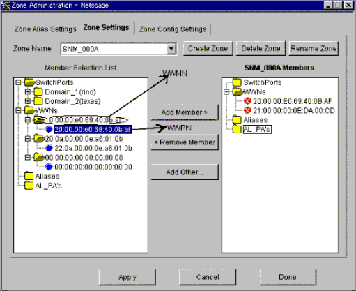
The zoning setting can be defined in the Zone Administration window of WEBTOOLS of the Fibre Channel switch. Note that settings in WEBTOOLS are dependent on the device and firmware.
For example, in the WEBTOOLS window of SN200M40 (v2.4) shown below, WWPNs are the values indicated by blue round disks on the Member Selection List and WWNNs are the values displayed next to the folder icons above the blue round disks.
The device cannot be detected.
Check whether the SNMP Community settings on the device side agree with the settings of this product. For details, see "6. SNMP community setting".
For devices that do not support [Detect device in subnet] as described in "1.3.5 Support levels", use [Detect by IP address] with the IP address specified.
Check whether the Ethernet port communication speed has been set correctly.
When the SNMP connection authorization list is set up, make sure to include authorization for access from the manager.
The physical connection line of the FC cable is not displayed.
Check whether all the Fibre Channel switches connected in cascade are registered in this product. Register all the Fibre Channel switches that have not been registered.
If the network communication with the device is disabled, the physical connection line cannot be displayed. Make sure that the device is powered on and there is no problem with the LAN connection. Furthermore, check whether the SNMP Community settings on the device side agree with the settings of this product. For details, see "6. SNMP community setting".
If the network communication is disabled because of device replacement or maintenance, the physical connection line is not displayed.
An error in an access path is displayed (in red).
A warning for a device is displayed (in yellow).
Check whether a hardware error (FC port, FAN, power supply, temperature, etc.) has occurred.
Check whether a monitoring state in device properties is "Invalid password". If so, the password on the device side has been changed. Refer to "2. User name and password for Fibre Channel switch control" and change the registration information of this product.
When the device is powered on or rebooted, initialization is performed in the device. While the initialization is being performed, if [Refresh] is executed, a warning message for the device may appear. If no error occurs on the device, execute [Refresh] again after the initialization of the device. The display then becomes normal (in green).
A warning for an access path is displayed (in yellow).
There is no zoning setting for configuring the access path.
If a monitoring state in device properties is "Invalid password," see "A warning for a device is displayed (in yellow)".
An error in an access path is displayed (in red).
A warning for a server node is displayed (in yellow).
When replacing a device
When changing SNMP Community of a device
See "6. SNMP community setting".
When changing the password of a device
When a device disappear from domain view
If a device network is not accessible, the device icon will disappear from the domain view. Refer to "The physical connection line of the FC cable is not displayed" for details. In this case, the device may be displayed on SAN view.
When PG-FCD101 or PG-FCD102 is not displayed
Check whether there are zoning settings in the Fibre Channel switch that is connected to PG-FCD101 or PG-FCD102. If there are no zoning settings, refer to "5. Zoning setting" and then create a temporary zoning.
The SN200, Brocade Fibre Channel switch can define six monitoring device addresses (SNMP Trap transmission places) per device and a different SNMP Community name for each of these addresses. This software product uses "public" for the entry that is set for the SNMP Community name. If this entry is already used, this software product overwrites it. If the SNMP Community name on the device side has been changed from "public" and the settings of this product have been changed accordingly, the entry with the changed SNMP Community name is used.
The SN200, Brocade Fibre Channel switch features the QuickLoop function that accomplishes FC-AL hub emulation. However, this software product does not support Fibre Channel switches for which this function is enabled.
This software product can control access paths to the GR740D (including the Fibre Channel switch). Note that the Fibre Channel switch of the GR740D cannot be connected in cascade to another Fibre Channel switch.
This software product communicates with the Fibre Channel switch using SNMP and telnet.
Recommendation of Fibre Channel switch redundancy (cascading).
At present, the Fibre Channel switch zoning information cannot be restored from the database of this software product. Therefore, multiple Fibre Channel switches must be connected in cascade to prevent the zoning information stored on the Fibre Channel switches from being erased. The zoning information is stored separately on each of the Fibre Channel switches connected in cascade. Even if one of the Fibre Channel switches fails, the zoning information is stored by the other switches.
The Fibre Channel switch zoning information is changed using the access path setting. When cascade connection is not used, be sure to save the device configuration information (configUpload file) after making changes in the settings. For details on storing configuration information, refer to the manuals that come with the device.
To manage Fibre Channel switches with this product, all the Fibre Channel switches that are connected in cascade must be registered with this product. If any Fibre Channel switch is connected in cascade but not registered with this product, the SAN environment cannot be correctly managed.
Use the manual embedding function to register the SN200 model 250M and Brocade AP7420 Fibre Channel Switches as Fibre Channel Hub devices. This registration makes SNMP Trap fault monitoring available to the Fibre Channel Switches.
In consideration of incompatibility of Fibre Channel switch firmware, ETERNSU SF Storage Cruiser checks the firmware version number.
If ETERNUS SF Storage Cruiser detects firmware that it does not support, all functions including the configuration management is restricted.
The following message is output to the event log. (XXXXXX is the version number of the detected firmware.)
"Unsupported Firmware Version XXXXXX"
Contact your Fujitsu CE or SE because patches need to be applied to ETERNUS SF Storage Cruiser.
The FC routing function
The FC routing function is not supported.
If a cascade is connected using the FC routing function, the cascade connection line is not displayed in the client window.
For this reason, an error is displayed (in Red) for the access path that goes through the cascade connection line, and a warning is displayed (in Yellow) for the server node that is used to configure the access path.
The FCIP tunneling function
For GbE ports that are used in the FCIP tunneling function, 8 virtual ports per single GbE port are displayed in the client window.
A warning is displayed (in Yellow) in the client window for the FC ports for which the FCIP tunneling function is disabled. Monitor the occurrence of errors using SNMP Trap.
This product supports the ETERNUS VS900 Virtualization Switch (a virtualization switch device).
For the system design and configuration building of the VS900, refer to the "ETERNUS SF Storage Cruiser User's Guide for Virtual Volume Management".
Brocade SMI Agent
SMI-used for VS900 management. SMI-S requires Brocade SMI Agent for VS900 management. Download Brocade SMI Agent and the related user's guide from http://storage-system.fujitsu.com/ (Fujitsu Storage System Information site), and then install it on your system according to said user's guide.
Brocade SMI Agent can be used on the same administrative server as the site manager of ETERNUS SF Storage Cruiser. Brocade SMI Agent must be started up on every node that constitutes the cluster when using Brocade SMI Agent in a cluster system because it does not function as a cluster service. To search for a VS900 device, use the cluster-inherited IP address.
Fault Management
When Brocade SMI Agent stops, VS900 management and virtual storage management are disabled. Note that using the device polling function (that enables SNMP Traps to be directly received from the VS900 and ping commands directly executed on the VS900), however, makes fault management available.
The events below may be displayed when Brocade SMI Agent stops.
Unit status changed: OK
Unit status changed: Warning
Unit status changed: Error
These events indicate that a device cannot communicate with the VS900 as a configuration management and that a virtual storage management, but can communicate with the VS900 via the device polling function. Moreover, when a device can communicate directly with the VS900, said device can also receive SNMP Trap events from the VS900.
The event below may be displayed regardless of whether Brocade SMI Agent is running.
Note that this event indicates that a device cannot communicate directly with the VS900 or receive SNMP Trap events.
Connection Timeout
proxy Switch
Brocade SMI Agent communicates with a certain Fibre Channel Switch in a fabric (or group of Fibre Channel Switches in a cascade connection). This Fibre Channel Switch is called a proxy switch.
Brocade SMI Agent is used to select and set a Fibre Channel Switch as a proxy switch. To manage multiple fabrics, specify as many proxy switches as the number of fabrics to be managed.
If a proxy switch fault or related abnormality causes a communication error between Brocade SMI Agent and a proxy switch, configuration management and virtual storage management are disabled just like when Brocade SMI Agent stops.
If a communication error occurs between Brocade SMI Agent and a proxy switch, you must first remove the cause of the communication error, and then restart the Brocade SMI Agent program.
The same symptom occurs when a cascade connection of Fibre Channel Switches in the fabric is broken by a disconnected FC cable or FC port fault. Restore the connection and restart the Brocade SMI Agent program.
SNMP Trap Event
The VS900 supports SNMP Traps through Fibre Alliance MIB. For details of SNMP Traps, refer to "2.7.1 Explanation of Fibre Alliance MIB Support Device Events" in the " ETERNUS SF Storage Cruiser Event Guide".
The cascade connection line
The physical connection line between the VS900 Virtualization switches is not displayed.
The device cannot be detected.
Please confirm whether neither Internet Protocol address of the server that Brocade SMI Agent is installed nor information on Brocade SMI Agent (NameSpace and Login account and Login password and Port Number etc.) are wrong. There is a possibility that the problem solves if Internet Protocol address that you specified for the device detecting is changed. (When the server in which Brocade SMI Agent is installed has two or more Internet Protocol addresses.)
Please confirm Brocade SMI Agent has started. Moreover, the device might be detected by restarting Brocade SMI Agent.
Please confirm whether information set to Brocade SMI Agent is correct. To make set information effective, you should restart Brocade SMI Agent.
Please refer to Installation Guide on Brocade SMI Agent for the setting of Brocade SMI Agent.
The device cannot be registered.
Please confirm whether information on VS900 set to the hosts file of the administrative server is correct. The hosts file is in the following.
Solaris ,Linux: /etc/hosts
Windows: %SystemRoot%system32\drivers\etc\hosts
Please confirm whether information on the administrative server is correctly set to VS900. It is necessary to reboot VS900 to make set information effective.
Please refer to "ETERNUS SF Storage Cruiser User's Guide for Virtual Storage Conductor "for the setting of the administrative server concerning VS900. Please refer to "ETERNUS VS900 Model 200 System Build Procedure" for the system construction procedure of VS900.
The product does not support a function to set an access path to the VS900. To build a SAN environment including the VS900, use the Zone Administration window of WEBTOOLS of the VS900 or the telnet command for zone setting.
Among VS900 zoning information, only WWPN zoning information can be displayed. If any zoning other than WWPN zoning is configured, access paths and zoning information cannot be displayed.
This product does not support a function for automatically setting a SNMP Trap send destination address for the VS900. To set such an address, use WEBTOOLS or the telnet command.
This product does not support a function to monitor VS900 performance.
This product does not support a VS900 beacon function.
This product does not support a "Detect device in subnet" function for the VS900. Therefore, use the "Detect by IP address" function with an IP address specified instead.
For PRIMERGY BX600 Fibre Channel switchblade, refer to "4.2.1 SN200 (Brocade) Fibre Channel switch".
This product supports the ETERNUS SN200 MDS fibre channel switch and Cisco MDS fibre channel switch.
The following section explains the settings required beforehand for managing these fibre channel devices on this product. For detailed information on these items, see the manual supplied with the device.
IP address, subnet mask, and gateway address (required)
Specify the IP address of LAN, subnet mask, and gateway address. Log in to the fibre channel switch device from the serial port, and specify them using the ip address command. Use the following procedure to specify the IP address.
|
switch# config t switch(config)# ip default-gateway [gateway address] switch(config)# interface mgmt 0 switch(mgmt 0)# ip address [IP address] [subnet mask] switch(mgmt 0)# exit switch(config)# exit |
SysName (recommended)
Register the device name for the fibre channel switch management. This device name is used as SysName of this product. This name should not overlap with other target items for management. Log in to the fibre channel switch, and specify the device name using the switchname command. Use the following procedure to specify the device name.
|
switch# config t switch(config)# switchname [device name] switch(config)# exit |
This product uses the fibre channel switch and the Community name "public" for communication. It uses "public" for reading the device information.
The Community name "public for this fibre channel switch is not registered at factory shipment. Use the following procedure for registering the Community name.
|
switch# config t switch(config)# snmp-server community public switch(config)# exit |
To change the SNMP Community name, change the setting of the device, and also change the setting of this product accordingly. For information on the settings of this product, see "Appendix D Customization".
SNMP Trap send destination setting
SNMP Trap is used for error monitoring. However, this fibre channel switch does not support the automatic setting function of the SNMP Trap send destination address. Register the SNMP Trap send destination address by using the following procedure.
|
switch# config t switch(config)# snmp-server host [IP address of the site manager] traps version 1 public switch(config)# exit |
SNMP Trap filter setting
The SNMP Trap filter for this fibre channel switch is set up at factory shipment. However, this product cannot perform proper error monitoring with the SNMMP Trap filter setting at factory shipment. Change the SNMP Trap filter setting by using the following procedure.
|
switch# config t switch(config)# snmp-server enable traps entity fru switch(config)# snmp-server enable traps fcdomain switch(config)# snmp-server enable traps license switch(config)# snmp-server enable traps vrrp switch(config)# snmp-server enable traps link ietf-extended switch(config)# exit |
When the device cannot be detected
Check whether the SNMP Community settings on the device side match the settings of this product. See "3. SNMP Community setting".
Check whether the Ethernet port communication speed has been set correctly.
When the physical connection line of the FC cable is not displayed
If the network communication with the device is disabled, the physical connection line cannot be displayed. Make sure that the device is powered on and there is no problem with the LAN connection. Furthermore, check whether the SNMP Community settings on the device side agree with the settings of this product. For details, see "3. SNMP community setting".
If the network communication is disabled because of device replacement or maintenance, the physical connection line is not displayed.
When a warning for a device is displayed (in yellow)
Check whether a hardware error (FC port, FAN, power supply, temperature, etc.) has occurred.
When the device is powered on or rebooted, initialization is performed in the device. While the initialization is being performed, if [Refresh] is executed, a warning message for the device may appear. If no error occurs on the device, execute [Refresh] again after the initialization of the device. The display then becomes normal (in green).
When replacing a device
When changing SNMP Community of a device
See "3. SNMP Community setting".
Use SNMP protocol version 1 for managing the device. For error monitoring with SNMP Trap, also use SNMP protocol version 1.
The management is performed with SNMP communication only. You don't have to log in to the device through TELNET. When you register with this product, you don't have to enter your user name or password.
Use the ping command for polling monitoring.
Zoning management is not supported. For information on how to display the zoning information or to set up zoning, see the manual supplied with the device. When the access path is set up, only the settings of server and storage are changed.
The operations of cascade connection are not supported. Even if the device is connected in cascade, the information about cascade connection is not properly displayed. As a result, the access path through the cascade connection is not properly displayed.
The access path display of a manually embedded device is not supported.
On the related management window, the path search function and End to End list display function are not supported.
The performance information cannot be referenced using Systemwalker Service Quality Coordinator.
The beacon function is not supported.
This product supports McDATA Fibre Channel switch.
The items that must be set in the device to manage these Fibre Channel devices in this product are explained below. For details about these items, refer to the manual included with the device.
IP address, subnet mask, and gateway address (required)
The LAN IP address, subnet mask, and gateway address are set. Log on to the Fibre Channel switch device from the serial port, and configure the settings using the config ip ethernet command. Set the IP address using the following procedure.
switch# config ip ethernet [IP address] [Gateway address] [Subnet mask] |
Domain name
A domain name is a unique name defined for a Fibre Channel switch in a SAN. Such names are necessary for a cascade connection of multiple Fibre Channel switches.
Set a value that is not duplicated inside the Fibre Channel switch to be cascaded. To use a cascade connection, log on to the Fibre Channel switch, and configure the settings using the config switch prefDomainId command. Set the domain name according to the procedure shown below.
SysName (recommended)
Register the device name used for Fibre Channel switch management. This device name is used as SysName in this product. It is recommended that you register a name that is not a duplicate of another management target.
Log on to the Fibre Channel switch and configure the settings using the config system name command. Set the device name using the following procedure.
Switch# config system name [Device name] |
SNMP community settings (required)
This product uses the Fibre Channel switch and the SNMP Community name "public" for communication. It uses "public" for reading the device information.
The SNMP Trap send destination address must also be specified for the command used to set the SNMP Community name. For this reason, the settings shown in "5.SNMP Trap send destination settings" below are also required.
Set the SNMP Community name using the following procedure.
Switch# config snmp addCommunity [Registration number] public enabled [SNMP Trap send destination address] 162 |
To change the SNMP Community name, change the device settings, and change the settings of this product to match. For details about changing the settings of this product, refer to "Appendix D Customization".
SNMP Trap send destination settings
Although SNMP Trap is used in fault monitoring, the SNMP Trap send destination address automatic settings function is not supported for this Fibre Channel switch. Register the SNMP Trap send destination address using the following procedure.
switch# config snmp addCommunity [Registration number] public enabled [SNMP Trap send destination address] 162 |
When a device cannot be detected:
Check whether the SNMP Community settings on the device side match the settings of this product.
For details, refer to "4. SNMP Community setting".
Check whether the Ethernet port communication speed has been set correctly.
When the physical connection line of the FC cable is not displayed:
If the network communication with the device is disabled, the physical connection line cannot be displayed. Make sure that the device is powered on and there is no problem with the LAN connection.
Furthermore, check whether the SNMP Community settings on the device side match the settings of this product. For details, refer to "4. SNMP Community settings".
The following occurs if the network communication is disabled because of maintenance, for example, for device replacement.
When a warning for a device is displayed (in Yellow):
Check whether a hardware fault (for the FC port, FAN, power, or temperature) has occurred.
Initialization processing is performed internally in the device when the device is powered on or restarted.
If the [Refresh] operation is executed during initialization processing, a warning may be displayed for the device.
If an error has not occurred in the device, normal display (in Green) can be achieved by executing [Refresh] again after initialization processing in the device is complete.
When replacing a device:
Refer to "8.2.1 Replacement of Fibre Channel switch".
When changing the SNMP Community of a device:
Refer to "4. SNMP Community setting".
Devices are managed using SNMP protocol version 1. SNMP Trap fault monitoring also uses SNMP protocol version 1.
Since management is only performed using SNMP communication, there is no TELNET logon to the device. For this reason, there is no need to enter a user name or password when registering the device this product.
ping is used for the polling monitoring.
Zoning management is not supported. Before displaying zoning information or configuring zoning settings, refer to the manual included with the device first. If the access path has been set, only the settings for server and storage are changed.
Display of the manually embedded device access path is not supported.
The path search function and the End to End list display function are not supported in the relationship management window.
The performance management function is not supported.
The beacon function is not supported.
140 ports are used for McDATA Intrepid 6140 Fibre Channel switch, but 144 ports are displayed in the client window. Of these, 4 ports, numbers 128 to 131, are ports that do not actually exist. This port information in the window is all dummy information.
12 ports from the 132nd to the 143rd of the McDATA Interpid 6140 are implemented on the back side of the device, but all ports are displayed in the client window as they are implemented on the front side.
To manage the ETERNUS8000 series, the ETERNUS6000 series, the ETERNUS4000 series, the ETERNUS3000 series, ETERNUS2000 series and GR series with this software product, set up devices while keeping in mind the points listed below. Read the term "ETERNUS VD800 disk array unit" in this manual as "ETERNUS3000 series".
Note: For settings details, refer to the ETERNUSmgr/GRmgr User's Guides supplied with ETERNUSmgr/GRmgr of each device, such as the "ETERNUSmgr User's Guide," "GR710/GR720/730 GRmgr User's Guide," and "GR740 GRmgr User's Guide". For the GR820/840, GRmgr must be purchased separately.
root password setting
Set the root password for logging in to ETERNUSmgr/GRmgr.
Community setting in SNMP (Agent) environment settings
This software product communicates with the GR/ETERNUS product by using "public" for the Community name at an initial value. Therefore, the Community name setting on the GR/ETERNUS product side must be either of the ones explained below a and b. Note that the Community name can be changed. For information on changing the Community name, see below c and "SNMP_COMMUNITY_NAME_FOR_IP" parameter in sanma.conf at "Appendix.D Customization".
Any Community is not set. (initial)
"Public" (Access: read Only, address: all hosts, and view: all Object) is set by an initial value.
Specify "public" for the Community name explicitly.
In this case, specify either the IP address of the administrative server on which Manager is installed or 0.0.0.0 (to receive messages from all hosts) as the IP address.
Specify other than "public" for the Community name explicitly.
The administrative server is specified with the Community name and the administrative server's IP address. However, when the manager is running in a cluster system, the manager communicates with ETERNUS/GR by using the physical IP address of the cluster system, therefore the Community setup are described by the same number as the physical IP addresses.
Example: "ssc" is the specified Community name for SNMP communication with the operation management server (IP Address: 10.10.10.10).
community ssc 10.10.10.10
Example: "ssccom" is the specified Community name for SNMP communication with the operation management server operating as a cluster system operation (physical IP_A: 10.10.10.11, physical IP_B: 10.10.10.12).
community ssccom 10.10.10.11
community ssccom 10.10.10.12
Trap setting in SNMP Agent Configuration Setting
Since the manager's SNMP Trap receiving module has not judged this Community name, all SNMP Traps sent to the administrative server can be received. Even in an environment where the Community name is specified other than "public", it is not necessary to change this community name in trap setting. The Community name of the trap destination is recommended to be set as "public", not same as the Community name of SNMP Community under the consideration of security.
If the maximum number of SNMP Trap transmission places of the ETERNUS/GR is already registered, no new IP address can be added. Therefore, make sure that the number of SNMP Trap transmission places is less than the maximum number.
Device name setting (SysName) in SNMP (Agent) environment settings
Register a nickname for storage management. This software product uses this value as SysName.
Network environment settings (excluding the GR740,820,840)
If the administrative server resides outside the location indicated by the IP address, subnet mask, gateway, and subnet, the subnet of the opration management server must be registered as the destination network address.
If an administration server is in a cluster;
If you specify the IP address of an administration server as a destination network address, specify both physical IP address of each node on administration servers in a cluster and IP address taken over.
Logoff
After completing definition of the settings with ETERNUSmgr/GRmgr, be sure to log off from ETERNUSmgr/GRmgr. In the ETERNUS8000, ETERNUS6000, ETERNUS4000 and ETERNUS3000 series, ETERNUS2000 series, or in GR710/720, the registration of devices in this product and use of the Storage Volume Configuration Navigator device setup function are only possible when not logged onto ETERNUSmgr/GRmgr.
Access paths can be set from this software product even while a user is logged in to ETERNUSmgr/GRmgr. If a change to access path settings is made simultaneously from both ETERNUSmgr/GRmgr and this software product, configuration information of the device may be destroyed. Therefore, when changing access path settings from this software product, make sure that no setting change operation is in progress on the ETERNUSmgr/GRmgr side.
For this product, the host access control function of ETERNUS disk array devices and GR series devices is called the host affinity function, and zone numbers are called AffinityGroup numbers. Defining them with more global names such as these makes it possible to address future multivendor device management needs. For definitions of other names, see "A.1 Notational Conventions of Window Elements and Abbreviations".
To use this product to set the server node and storage access path (the SAN environment containing the Fibre Channel switch), refer to "6.3.3.1 Preparations". The following settings must also be configured in the device.
RAID settings
RAID group/LogicalVolume setup is executed using Storage Volume Configuration Navigator or ETERNUSmgr/GRmgr. For storage devices not supported by Storage Volume Configuration Navigator, execute the setup using ETERNUSmgr/GRmgr.
For details about Storage Volume Configuration Navigator, refer to "11.1.4 Operation procedure".
Affinity Group/Zone settings for storage
AffinityGroup/Zone is created in the storage device using Storage Volume Configuration Navigator or ETERNUSmgr/GRmgr. For storage devices not supported by Storage Volume Configuration Navigator, create AffinityGroup/Zone using ETERNUSmgr/GRmgr.
For details about Storage Volume Configuration Navigator, refer to "11.1.4 Operation procedure".
* Setting with ETERNUSmgr of the ETERNUS8000, ETERNUS6000 or ETERNUS4000 series (other than M40, M100)
Make AffinityGroup settings common within a storage system by using the [Set AffinityGroup] menu from the [Setting RAID/Setting Host] menu.
* Setting with ETERNUSmgr/GRmgr of the ETERNUS4000 (M80, M100) or ETERNUS3000 series (other than M50)
Make Affinity Group/Zone settings common within a storage system by using the [Append/Delete Zone(s)] menu from the [Setting RAID/Setting Host] menu.
* Setting with ETERNUSmgr/GRmgr of the ETERNUS3000 M50, GR710, GR720, GR730
Make Affinity Group settings that are based on the port setting or LUNMapping settings. To specify a port, select the port by using the [Set Host Interface Mode] menu from the [Setting] menu. To make LUNMapping settings, use the [Zone management] menu from the [Addressing mode] menu. Before making Affinity Group settings, make settings for [Host-Zone management].
* Setting with ETERNUSmgr of the ETERNUS2000 series. Set up a common Affinity Group within the storage from the "Host Affinity."
In ETERNUSmgr of the ETERNUS2000, a wizard format is used to set up from the AffinityGrop all the way to HostAffinity. However, the "HostAffinity"in "Step5: Select HBAs" will be set up as non-selection (no HBA allocation).
* Setting with GRmgr of the GR740, GR820, GR840
Make the zone settings common within a storage system by using the menu for Mapping settings.
Connection topology settings
Make the Fabric Connection setting (N port) for the FC-CA port to be connected with the switch.
* Setting with ETERNUSmgr of the ETERNUS8000, ETERNUS6000, or ETERNUS4000 series (other than M40, M100)
From the [Set CA Parameters] menu in the [Setting RAID/Setting Host] menu, select the FC-CA to be used for the SAN. Then, from [Connection Topology], select [Fabric Connection], and click the <Set> button.
* Setting with ETERNUSmgr of the ETERNUS4000 (M80, M100), ETERNUS3000 series (other than the M50)
From the [Set CA Port] menu in the [Setting RAID/Setting Host] menu, select the FC-CA to be used for the SAN. Then, from [FC Connection Settings], select [Fabric Connection], and click the <Set> button.
* Setting with ETERNUSmgr of the ETERNUS2000 series.
From the [Port] tab in the [Settings] menu, select a port from the port tree on the left window. Then from the [Connection Topology], select the [Fabric Connection] and click the <OK> button.
* Setting with GRmgr of the GR740, GR820, GR840
From the [CA Setting] menu, select the FC-CA to be used for the SAN. Then, disable loop connection.
Host interface settings
Make the host affinity setting (recommended) for the FC-CA. If "2. Affinity Group/Zone settings for storage" is executed using Storage Volume Configuration Navigator, the host affinity settings are essential.
* Setting with ETERNUSmgr of the ETERNUS8000, ETERNUS6000 or ETERNUS4000 series (other than M80, M100)
From the [Set CA Parameters] menu in the [Setting RAID/Setting Host] menu, select the FC-CA to be used for the SAN. Then, set [Affinity Mode] to ON (recommended), and click the <Set> button.
* Setting with ETERNUSmgr of the ETERNUS4000 M80, M100, ETERNUS3000 series (other than the M50)
From the [Set CA Port] menu in the [Setting RAID/Setting Host] menu, select the FC-CA to be used for the SAN. Then, from [Addressing Mode Settings], select [Host Table Setting Mode].
Since this software product automatically makes settings for [Append/Delete Authorized Host(s)] in [Host Table Setting Mode], no such setting need be made here. Lastly, click the <Set> button.
* Setting with ETERNUSmgr/GRmgr of the ETERNUS3000 M50, GR710, GR720, GR730
From [Set Host Interface Mode] in the [Setting] menu, select a port for this setting. If [Zone Management] in the [Addressing Mode] menu is enabled, check [Authorized hosts only] to enable it (recommended). If [Host-Zone management] is enabled, another setting need not be made. In both addressing modes, this software product automatically makes the setting for [Authorized hosts only] and HostAffinity setting (if [Zone Management] is selected, this software product automatically specifies values only when [Authorized hosts only] is enabled).
* Setting with ETERNUSmgr of the ETERNUS2000 series
From the [Port] tab in the [Settings] menu, select a port from the port tree on the left window. Next check the [Affinity Mode] box of the [General Setting] and click the <OK> button.
* Setting with GRmgr of the GR740, GR820, GR840
From the [CA Setting] menu, select the FC-CA to be used for the SAN. Then, enable (recommended) the security function.
Note that this software product automatically sets and deletes the Host WWN definitions and Host WWN-Affinity Group/Zone definitions of ETERNUS disk array devices, and thus settings need not be made manually.
To set the date-time for the device, perform the procedure shown below. If the date-time is set during performance monitoring, briefly stop performance monitoring and then restart it.
Stop performance monitoring of the device for which date-time is set.
Set date-time for the device.
After the date-time settings are complete, restart performance monitoring of the device.
To change the configuration for the device, the device configuration information kept by performance management must be updated. Update the configuration information according to the procedure in "7.2.11 Updating configuration information".
Unable to detect ETERNUS8000, ETERNUS6000, ETERNUS4000, ETERNUS3000, ETERNUS2000series, or GR series
This software product uses SNMP communication to find devices. Therefore, a storage device whose SNMP function is inactive cannot be detected. The storage device's SNMP function must be started.
Press the [Set] button in the ETERNUSmgr/GRmgr SNMP environment setting window. The SNMP function is started by once pressing the [Set] button. Therefore, if the [Set] button is not pressed at all, the SNMP function remains inactive.
If the server running the manager is not defined as a destination server on the server running SNMP trap transmission, auto-detection may not work. If this is the case, check the SNMP trap transmission settings and make sure the server running the manager is defined.
If the SNMP community name is changed and Manager is in the cluster environment, settings on the storage device side may be incorrect. See "Changing SNMP community name" given below.
Check the network environment, access authorization and communication mode settings referring to section "4.3.1.1 Setting" for details. Make sure that one communication mode is not set to "Auto Negotiation" while the other is set to "Full (full duplex)"
Unable to detect GR740, GR820, GR840
Check whether GRG (GRGateway) is active on the maintenance PC. If it is inactive, execute GRG.exe. Also, register GRG.exe in the Startup menu.
If the SNMP community name is changed and Manager is in the cluster environment, the settings on the storage device side may be incorrect. See "Changing SNMP community name" below.
Changing SNMP community name
This software product implements SNMP communication using the community name public by default. If "Set SNMP Agent Environment"-"Set Community" is not set at all for ETERNUS and GR storage devices, "public" (access: readOnly, address: all hosts, view: all objects) has been set as the initial value. If at least one community is set, the product software communicates with only the specified community settings.
When the SNMP community name for the ETERNUS and GR storage devices is to be changed, storage device settings are required.
See "2. Community setting in SNMP (Agent) environment setting" in "4.3.1.1 Setting".
Timeout occurs in communication.
Check the communication settings and make sure that one communication mode is not set to "Auto Negotiation" while the other is set to "Full (full duplex)".
This product supports fault management (SNMP trap monitoring only) of the disk array ETERNUS SX300, ETERNUS SX300S. Follow the procedure below to register the disk array as a manually embedded device:
Registering the SANtricity installation server
SNMP traps of ETERNUS SX300 and ETERNUS SX300S are sent from the server on which the device management software SANtricity is installed.
The SANtricity installation server must be registered with this software product to perform SNMP trap monitoring.
Register the SANtricity installation server with this software product by using either of the following methods:
Install ETERNUS SF Storage Cruiser Agent on the SANtricity installation server, and then register the server as a managed server node.
Use the manual embedding function to register the SANtricity installation server as a manually embedded host
(Be sure to enter the IP address of the server node).
Registering the ETERNUS SX300, ETERNUS SX300S device
Use the manual embedding function to register the ETERNUS SX300, ETERNUS SX300S device with this software product.
The following information must be set for the registration:
Specify the device name marked in SANtricity in "Device name". (E.g. SX3RF2B-000001)
Note that monitoring cannot be performed correctly if the device name is incorrect.
Enter the IP address of the SANtricity installation server in "IP address".
SNMP trap setting
Set the trap transmission destination on the SANtricity installation server so that SNMP traps of ETERNUS SX300, ETERNUS SX300S will be sent to the operation management server.
If the operation management server is defined as a cluster, the logical IP address of the cluster needs to be set.
This product supports all functions of the LT270, LT250 and LT160 except performance monitoring. Note that this product does not have a function to automatically detect LT270, LT250 and LT160 devices. The LT270, LT250 and LT160 devices can be detected by specifying their IP addresses for Device Search.
Connection to a network
Make the settings to connect the LT270, LT250 and LT160 to a network, and then connect the devices to the network. At the same time, start up the SNMP Agent function. For details of how to make these settings, refer to the manuals supplied with the LT270, LT250 and LT160 devices.
Setting Community for SNMP Environment setting
Select "public" as the Community name (GET). The Community name can be changed as desired. To change the Community name, see "Appendix D Customization".
Name (SysName) of a device for SNMP (Agent) Environment setting
Specify a nickname for the LT270, LT250 and LT160 device for management purposes. This product uses Sysname for said nickname value.
SNMP Trap setting
Manager does not add the SNMP Trap transmission place that was set at the device's registration to the device. Therefore, use the LT270, LT250 and LT160 Management Software to specify the SNMP Trap transmission place as the IP address of the administrative server on which this product runs. When the administrative server is defined by a cluster, the logical IP address of the cluster must be specified.
Setting and displaying an access path
This product does not use the HostAffinity setting of the LT270, LT250 and LT160, but displays access paths by using SwitchZoning or StorageAffinity of the server node.
This product supports the collaboration of Fault Management and the Management Software of tape library devices LT120, LT130 and LT230, HP Surestore Tape Library, and Overland Storage NEO 2000 Tape Library. The connection configuration is edited on-screen.
Connection to a network
Make the settings to connect the LT120, LT130, LT230, HP Surestore Tape Library, and Overland Storage NEO 2000 Tape Library to a network, and then connect these devices to the network. Similarly, make the settings to connect the built-in bridges of the LT130 and NEO 2000 Tape Library to the network, and then connect these bridges to the network. For details of how to make these settings, refer to the manuals supplied with the LT120, LT130 and LT230 Tape Library, and NEO 2000 Tape Library.
SNMP Trap setting
Use the Management Software of the LT120, LT130, LT230, Surestore Tape Library, and Overland Storage NEO 2000 Tape Library to specify the SNMP Trap transmission place as the IP address of the administrative server on which this product runs. When the administrative server is defined by a cluster, the logical IP address of the cluster must be specified. After making this setting, restart the devices.
Collaboration of Management Software
Use the Management Software (provided with the LT120, LT130 and LT230) for device management of such items as detailed device status and the various settings of the LT120, LT130 and LT230. The Management Software can be invoked directly by the LT120, LT130 and LT230 icon. Register each device in the resource view. From the Properties of Device Icon, select "Call management software" and click "Change". Specify the following names for the Management Software:
LT130, LT230 and NEO 2000 Tape Library: "http://IP-address-of-IP-address"
LT120 and Surestore Tape Library: Refer to the manual supplied.
This product supports Automatic Device Recognition, Status Management, Management Window Correlation, and Draw FC Connection Lines of the bridge device Crossroads. Note that this product only supports "Initiator mode".
Connection to a network
Network environment setting
Set the IP address, subnet mask, and gateway address by referring to the user's manual supplied with the device.
User name and password for controlling the bridge device
The device uses user name "root" and password "password" by factory default. Change these values as desired. The user name and password are required for "Add Device" operation in the GUI window.
Setting Community for SNMP Environment setting
Select "public" as the Community name (GET). The Community name can be changed as desired. To change the Community name, see "Appendix D Customization".
SNMP Trap setting
The SNMP Trap settings function is not available.
Detailed settings inside the bridge device
This product collects and displays part of the physical configuration and the device status. For the other detailed management information, use the Web-based management tool. This tool can be invoked directly from this product by clicking the Bridge Device icon.
This product supports Status Management, Management Window Correlation, and Draw FC Connection Lines of the tape encryption device.
Connection to a network
Make the settings to connect the tape encryption device to a network, and then connect said device to the network. For details of how to make these settings, refer to the manuals supplied with the tape encryption device.
SNMP Trap setting
Use the Management Software used for SNMP Trap setting to the SNMP Trap transmission place as the IP address of the administrative server on which this product runs. When the administrative server is defined in a cluster, the logical IP address of the cluster must be specified. After making this setting, restart the device.
Detailed settings inside the tape encryption device
This product collects and displays part of the physical configuration and the device status. For other detailed management information, use the Web-based management tool. This tool can be invoked directly from this product by clicking the Tape Encryptor icon.
This product supports fault management and linkage to the Management Software for network disk array devices and the cache server NR1000. Embed a device and register its IP address by seeing "5.2.6 Registering a Manually Embedded Device".
Connecting to the network
Make the required settings for the cache server NR1000 to connect to a network, and then connect to the network.
For details on how to connect to a network, see the manual that comes with the NR1000 unit.
Activating SNMP
The device polling function uses SNMP to acquire the device status of the NR1000 series. Enable the SNMP function so that device information can be acquired using SNMP. For detailed information on making settings, see the manual that comes with the NR1000 unit.
"Public" is used as the default Community name, but any name can be set. To change the Community name, see "Appendix D Customization".
SNMP trap setting
Make the required settings on the NR1000 unit so that SNMP traps of the NR1000 unit will be sent to the operation management server.
If the operation management server is defined as a cluster, the logical IP address of the cluster needs to be set.
Management software cooperation
Use the attached management software for device management such as checking the detailed device status of the NR1000 unit and the various settings. The management software can be called directly from the NR1000 icon. After registering the device in the resource view, select the <Change> button of [Device management software] from the properties menu displayed after right-clicking the device icon to set the program pathname for the device management software to one of the following:
NR1000C: "http://device IP address:3132/"
NR1000F: "http://device IP address/na_admin/"
This software product supports fault management and management software linkage for the VD800 virtual disk controller.
Hierarchical control processor settings
Softek Storage Cruiser 1.2.1 (hereafter referred to as SSC) Agent is installed on the hierarchical control processor (server node) contained in the VD800.
To monitor the hierarchical control processor as a server node monitored by this software, make the following settings to register the hierarchical control processor with this software:
Make a setting in /etc/services.
SSC Agent communicates with the operation management server through LAN port number 4917 by default.
Therefore, include this port number in the /etc/services file as shown below to declare use of the port number.
If no port number is specified, SSC Agent is started with port number 4917.
[/etc/services file setting contents]
|
# service name port number/protocol name sscruisera 4917/tcp |
If the port number is already being used, change the port number to one that is not.
If changing the port number, however, use the one corresponding to the same service name set on the operation management server.
Make a setting in the /etc/hosts file.
Include an IP address that enables communication with the operation management server (manager).
In an environment in which IP addresses are converted (such as NAT), specify an IP address that enables communication from the operation management server, instead of the IP address of a server node.
[/etc/hosts file setting example]
|
10.10.10.10 spm-0-ext |
Specify the SSC Agent startup IP address.
Specify an IP address that enables communication with the operation management server (manager).
Specify the IP address defined in the /etc/hosts file of b. as the startup address in the following command:
|
# /opt/FJSVssagt/bin/setagtip -i startup IP address |
After executing the above command, stop and restart SSC Agent.
Execute the following commands to stop and restart SSC Agent:
Stopping SSC Agent
|
# /opt/FJSVssagt/bin/pstorageagt |
Starting SSC Agent
|
# /opt/FJSVssagt/bin/sstorageagt |
Search for and register the hierarchical control processor.
Select the base domain of the resource view, right-click in the base domain view, and select [Register]-[Register Server].
In the displayed view, specify the IP address (Agent startup IP address) used for communication with the manager of the hierarchical control processor, and click the <OK> button.
When search and registration processing is completed, the hierarchical control processor (server node) icon is displayed in the base domain.
Fibre Channel switch, disk array device, and tape library device contained in the VD800
[Device settings]
Construct and set up the environment for the Fibre Channel switch, disk array device, and tape library device contained in the VD800, as described in this manual.
[Device registration]
Referring to "5.2.1 Device search" to register the devices.
|
Contents
Index
|