| ETERNUS SF Storage Cruiser User's Guide 13.2 - Solaris (TM) Operating System / Linux / Microsoft(R) Windows(R) - |
|
Contents
Index
|
Configuration management is made by using each view of the resource view and the Correlation window. This chapter explains how to use each window.
The resource view consists of the following views:
Main View: The view shown by click the first menu at the left tree.
Category View: There are three categories in the MainView tree; they are Server, Storage and SAN.
Domain View: When a domain icon is double-clicked in the server category or storage category view, device icons related to a device that is registered in that domain are displayed.
SAN View: When a SAN device type is selected from the SAN category view, devices of that device type that can be accessed with a login account are map-viewed.
Side View: The view shown by click server domain view, storage domain or double click the device in SAN View
This view is used to display all the devices that are registered on the resource view. The category icons of the managed devices are displayed.

By clicking [Refresh] from [View], the latest SAN status of all devices is loaded and displayed.
When a device is connected with a Fibre Channel, a physical connection line is automatically displayed. (Even if two physical Fibre Channel cables are connected, one line is indicated.)
Each device icon can be freely positioned. It should be positioned in an easy-to-manage location. The device icon in each view is displayed depending on the device status as follows.
|
Icon state |
Color |
Icon |
Description |
Action to be taken |
|---|---|---|---|---|
|
normal |
Green |
|
The device is operating normally. |
None |
|
warning |
Yellow |
|
An attention-level error was detected in the device. Resources can be available. |
Replace the faulty part, and execute recovery processing. ->8.1 Windows Displayed in the Event of a Fault and Troubleshooting |
|
error |
Red |
|
An error was detected in the device though the cause is not found. Resources are not available. |
Replace the faulty part, and execute recovery processing. ->8.1 Windows Displayed in the Event of a Fault and Troubleshooting |
|
stop |
Green |
|
Stop status. |
None |
|
fatal |
Red |
|
Faulty parts are detected in this resource. Resources are not available. |
None |
|
unknown |
Grey |
|
Status unknown |
None |
|
timeout |
Gray |
|
The device is defined in this software product, but it cannot recognize it. The device properties displayed by the GUI are the values that were retrieved the last time that the device was recognized. However, if the device is a Fibre Channel switch that enters the timeout state, the GUI does not display the Fibre Channel physical line under the Fibre Channel switch. The GUI indicates errors for all access paths using the Fibre Channel switch because this software product cannot check the statuses of these paths. |
The power supply of the device may be off or Agent may not be operating; also, a LAN error may have occurred. If you changed the IP addresses manually, also refer to "9.1.2 Changing the operating environment" and perform operations to reflect the changes of the IP addresses. If the device uses the SNMP protocol for communication, the community name of the device may differ between the target device and admin server. If the community name of the target device has been changed, set the community name by referring to "D.2 sanma.conf Parameter", and reflect the setting file on this software product. ->Check the device status, and select [Refresh] from the menu. |
|
undefined |
Violet |
|
The device is undefined in this software product. |
Define the device. |
Revolving light icon lights when there is a change in the state of the displayed device. Revolving light icon is displayed as follows:
|
Revolving light icon state |
Color |
Icon |
Description |
Action to be taken |
|---|---|---|---|---|
|
Information |
Green |
|
The state change occurs in the device displayed on the screen. |
Click the revolving light icon and update to latest information. |
|
Warning |
Yellow |
|
The trouble at the warning level occurs in the device displayed on the screen. |
Click the revolving light icon and update to latest information and recover. ->8.1 Windows Displayed in the Event of a Fault and Troubleshooting |
|
Error |
Red |
|
The trouble occurs in the device displayed on the screen. |
Click the revolving light icon and update to latest information and recover. ->8.1 Windows Displayed in the Event of a Fault and Troubleshooting |
|
Normal |
Grey |
|
There is no state change in the device displayed on the screen. |
None |
This software product automatically analyzes and displays the connection status of each Fibre Channel physical line between devices, such as that between a server node and a Fibre Channel switch and that between a Fibre Channel switch and storage.
The current version of this software product automatically displays the connection status of Fibre Channel physical lines between the devices listed in Table 6.3.
|
HBA |
Solaris OS PW008FC2A, |
Solaris OS LP-9000, |
Windows PG-FCD101, |
Windows LP-9000, |
Linux PG-FC105, |
HP-UX A6795A, AB378B, |
|---|---|---|---|---|---|---|
|
Fibre Channel switch |
Yes |
Yes |
Yes |
Yes |
Yes |
Yes |
|
Fibre Channel hub |
Yes(*1) |
No |
Yes(*1) |
No |
No |
No |
|
One-to-one connection |
Yes |
No |
Yes |
No |
No |
No |
*1 These are converted to individual lines connecting several HBAs and a CA.
When a category icon is double-clicked on the resource view, or SAN device type registered in the category (server, storage, or SAN) is displayed in the map area.
When the SAN category is selected, all devices that can be accessed with a login account are displayed on the tree.
When a base domain icon is double-clicked in the server category or storage category view, device icons related to a device that is registered in base domain are displayed. (Even if two physical Fibre Channel cables are connected, one line is displayed.)
By clicking [Refresh] from [View], the latest status of a device that is managed in the base domain is displayed.

Each device icon can be freely positioned. It should be positioned in an easy-to-manage location.
When a SAN device type is selected from the SAN category view, devices of that device type that can be accessed with a login account are map-viewed.
Double-clicking a device icon in the main view, domain view or SAN view displays a view showing Fibre Channel port details such as the access paths, physical lines, HBAs, and CAs of devices logically related to the selected device. This view can be used to manage access paths and check the statuses of HBAs and CAs.

Note that double-clicking a switch icon disables the display and setting of an access path.
In the virtual storage environment, this view screen shows no device that is logically related to each device.
|
Icon state |
Color |
Description |
Action to be taken |
|---|---|---|---|
|
normal |
Green |
The server node has the HBA. |
None |
|
warning or error |
Yellow (Be sure to check the status because this icon color is the same as that indicating "This access path must be inherited".) or red |
All access paths of the HBA are blocked, the FC cable is loose, or one other such error has occurred in the HBA. |
Replace the faulty part, and perform recovery processing. ->8.1 Windows Displayed in the Event of a Fault and Troubleshooting |
|
timeout |
Gray |
The previously recognized HBA is not recognized. |
If the HBA is in a state other than the timeout state, check if the HBA is correctly installed in the device. If the HBA has already been removed from the device, select the HBA, and click [Delete HBA]. |
|
The access path must be inherited. |
Yellow (Be sure to check the status because this icon color is the same as that indicating "Warning".) |
This software product detected replacement of the HBA. (An HBA with a different WWPN is mounted in the same slot of the server node.) |
Reconstruct access paths according to the WWPN of the new HBA. |
|
Icon state |
Color |
Description |
Action to be taken |
|---|---|---|---|
|
normal |
Green |
The CA is properly mounted. |
None |
|
error |
Red |
CA operation has degraded. |
Replace the faulty part, and execute recovery processing. ->8.1 Windows Displayed in the Event of a Fault and Troubleshooting |
|
timeout |
Gray |
The previously recognized CA cannot be recognized. |
The power supply of the device may be off or Agent may not be operating; also, a LAN error may have occurred. |
The port numbers of ETERNUS SN200 model 320 (Brocade Corporation Brocade 12000) and ETERNUS SN200 model 340 (Brocade Corporation Brocade 24000) are displayed as numbers 0 to 15 to agree with real machine indications.
However, if an error occurs in a port, the port serial number is displayed as indicated below. It is, therefore, difficult to determine which port failed. To solve this problem, port numbers in the switch port information to be list-displayed are displayed using serial numbers to make it easy to determine real machine port locations from the event information.
The operation is explained below.
Information that indicates a port error is displayed in the event log display.
In the event log, the information is displayed by using the serial number of the port.
Using the event information, open the side view for the switch of the port where the error occurred.
From [View] in the menu, select [Change]-[Map/List View(D)].
[Map/List View(D)] does not need to be selected if it is already selected.

The switch port information is displayed in the list view.
From the port number list in the switch port information, find the port number that is reported by the event.
Select the row of the port number that is reported by the event.
The port in the map that corresponds to the port number is selected to be displayed.
From the slot location and port number of the port that is selected in the map, the real machine port location where the error occurred can be recognized.
This section explains how to edit the lines indicating physical connections of manually embedded devices.
Open the Manual Configuration window.
Switch to the Main view, SAN view and select [Manual configuration window] from [File] in the menu or select [Manual configuration window] in the pop-up menu. All of the Fibre Channel switches, bridges, or routers are displayed.
Embedding a Fibre Channel switch port in a manually embedded device.
An UnknownFC port among Fibre Channel switch ports displayed in the Manual Configuration window indicates port connection place information that cannot be recognized. Click the UnknownFC port, and drag and drop it on the manually embedded device. (This operation cannot be performed by selecting [Physical Line]-[Edit(M)] from the [Operation(C)] menu.) A dialog then appears, and you can enter port information in this dialog. Enter port information, including options that can be recognized, in the dialog.
The left part of the figure below shows the status before an UnknownFC port of a Fibre Channel switch is dropped on a manually embedded test device. The right part shows the status after the UnknownFC port was dropped on the device.
Embedding an UnknownFC port of a Fibre Channel switch in a library or bridge device (including the connection between the bridge and library devices).
Click the UnknownFC port of the Fibre Channel switch, and drag and drop it on the library device (upper FC port of the LT series) or bridge device. (This operation cannot be performed by selecting [Physical Line]-[Edit(M)] from the [Operation(C)] menu.) A dialog then appears, and you can enter port information in this dialog. Enter port information, including options that can be recognized, in the dialog.
When connecting the bridge device to the library device, click the device icons such as the robot or tape icon, displayed on the bridge device, and drag and drop them as though they are on the library device.
The two figures below show an example of dropping port 2 (UnknownFC port) of Fibre Channel switch Switch on LT120 library device aa and an example of dropping port 0 (UnknownFC port) of Fibre Channel switch Switch on the boulder bridge. In these examples, the robot icon and tape icon of the bridge boulder are also dropped on the golden library.
Canceling manual embedding of an UnknownFC port.
To restore the UnknownFC port to its original state, right-click the set port/adapter, and select [Delete Registered Device] on the popup menu.
Close the Manual Configuration window.
Select [Exit] in [File] or select the [OK] button in the lower part.
When a change is made in the Manual Configuration window, a dialog box "Do you want to update the administrative server with the latest information?" is displayed. Select the [OK] button to refresh the information.

In most FC-AL one-to-one connections or router device, this software product cannot obtain connection information automatically. For this reason, it provides a function enabling editing and management of physical lines. The Manual Configuration window is used for the editing of physical lines. One-to-one connections require that each device port be recognized in advance and that the Manual Configuration window be displayed. Therefore, a manually embedded server node cannot be connected to a manually embedded storage system without a Fibre Channel switch.
Open the Manual Configuration window.
Switch to the Main view, SAN view and select [Manual configuration window] from [File] in the menu or select [Manual configuration window] on the pop-up menu. Manually created devices and their related devices and devices with an UnknownFC port connected are displayed.
Devices related to this operation are displayed in the Manual Configuration window.
On the [Operation(C)] menu or the popup menu, select [View Device]-[Add]. The dialog for selecting devices to be displayed appears. Devices registered with this software product are displayed in the left frame of the dialog. Select a target device, and click the [>>] button to move the device to the right frame.

Change the sizes of all device icons to be used to the port display size.
Select a device icon, and set [Change Detail View] to [ON] from the popup menu.
Change the edit mode to physical line edit mode.
From the [Operation(C)] menu, select [Physical Line]-[Edit(M)].
Connect ports that are actually connected.
To connect a port that is actually connected but whose connection is not displayed in the window, click the port to select it, drag it to the corresponding remote port, and drop it there. (This operation must be performed in physical line edit mode.)
Close the Manual Configuration window.
Select [Exit] in [File] or select the [OK] button in the lower part.
When a change is made in the Manual Configuration window, a dialog box "Do you want to update the administrative server with the latest information?" is displayed. Select the [OK] button to refresh the information.
The router device can connect a physical line only between switch devices. Moreover, only one physical line can be connected between one router device and one switch.
If the physical line between HBA port of a connected server node and FC-CA port of storage is not automatically displayed in port extension mechanism (hub) connection environment, execute the editing of the connected physical line by the following procedure:
Embedding the port extension mechanism (hub) by the manual embedding function of this software product.
Display port extension mechanism (hub) unit by the manual embedding function in this software product.
Switch to the Main view, SAN view and select [Manual configuration window] from [File] in the menu to display the Manual Configuration window.
Select [Hub Device] in [Create New Device] from [Operation(C)] in menu bar or from popup menu.
Select [Others] in the dialog to fill in the product type.
Specify the following information in the dialog to fill in device information. The specified information is displayed as property information of this software product.
Embedding information tag: Specify an arbitrary device name in the device name and select "4" as the number of ports.
Option tag: Fill in the product company name and the product name (optional) and don't fill anything in for the IP address. Hub is displayed by clicking the [OK] button.
Because a port extension mechanism (hub) physically includes two port units (hubs), each with four ports, re-execute the steps from b to create and display a total of two hubs (device names should be different). In the following example, two hubs are created:
Connecting the lines with the manual embedding function in this software product.
Draw the physical lines between the created port extension mechanism (hub), HBA ports and FC-CA ports.
Display the device connected with the port extension mechanism (hub)
Select [Add] in [View Device] from [Operation(C)] in menu in the Manual Configuration window or in popup menu and choose server nodes and ETERNUS3000 M50, GR710 devices which connected with the port extension mechanism (hub) from the "Availavle Devices" frame and then add them on the other side of the "Devices to Show" frame.
The added devices are displayed in the Manual Configuration window by clicking the [OK] button.
Select [Edit(M)] in [Physical Line] from [Operation(C)] in menu bar or in popup menu. It is not necessary to select, if the check mark is already displayed at [Edit(M)]. The physical lines can be edited while the check mark is displayed at [Edit(M)].
Select the port that is to be connected, drag and drop it to draw the physical line to the destination port.
The physical line connected to the destinotion port is displayed after drag and drop operation.
The physical line created as described is between the port extension mechanism (hub) and the storage FC-CA port or the HBA port of the server node. If the port number of the port extension mechanism (hub) differs from the actual port number of the device, this is not a problem. The created physical line can be deleted and another physical line can be drawn. To delete the physical line, select it, right-click it, and select [Delete] from [Physical Line].
Create all the physical lines of ports that should be connected to the port extension mechanism (hub), then select [Exit] in [File] in the menu of the Manual Configuration window or select the [OK] button in the lower part to close the Manual Configuration window.
A dialog box "Do you want to update the administrative server with the latest information?" is displayed. Select the [OK] button.

The created physical lines and port extension mechanism (hub) are displayed by the click of the [OK] button.
The following figure shows the Side view of storage. The storage connection environment includes port extension mechanism (hub) devices (two manually embedded hub devices), an ETERNUS3000 M50, and two server nodes. The physical lines of their connections were created and edited in the Manual Configuration window.
Call Management Software corresponding to a device icon of this software product. Select and right-click the device icon to display a popup menu. Selecting [Call management software] on this popup menu calls the Management Software.
If the device that you want to manage is not an ETERNUS 3000 or GR device, you can change the Management Software call method.
To change the Management Software call method, edit the method by clicking the button that opens the Management Software Change dialog from "Property" of the each device. (This software product supports both URL call and direct command execution.) The telnet can be started from the Management Software by describing it by the following formats.
Example: telnet://connected-server-name (Or, connected-server-IP-address)
This software product provides the Beacon function that causes the LED(s) of a device to blink as a way of determining which device actually corresponds to the selected device icon. This function can be used even while devices are in operation.
Use of this method for recognizing devices and support of the function are explained below. Double-click a device icon of this software product to display the Side view of the device. Select and right-click the devices listed below in the Side view to display their popup menus. Select [Blink Beacon]-[Start] from each popup menu so that the Beacon LED(s) of a device blinks for three minutes. No menu with this selection is available for devices that do not support this function. To stop blinking, select [Blink Beacon]-[Stop] from the appropriate popup menu.
Fibre Channel switch: LEDs of all the ports blink in turn.
Fibre Channel hub (Gadzoox): The power indication LED blinks.
HBA (GP7B8FC1A, GP7B8FC1-G and GP7B8FC1): The two LEDs (LINK and CHK) of the host bus adapter (HBA) blink at the same time.
HBA (PW008FC2A, PW008FC2-G, PW008FC3 and SE0X7F11F): The LINK LED of the HBA blinks.
HBA (SE0X7F12F): The selected host bus adapter (HBA) port LINK LED blinks.
CA and HBA (FC adapter) icons (including a manually embedded device) can be deleted. An access path cannot be inherited for deleted CA and HBA (FC adapter) icons.
Click the CA or HBA icon to be unregistered, and from the [File(F)] menu, select [Delete]. Alternatively, right-click the CA or HBA icon to display a popup menu, and select [Delete].
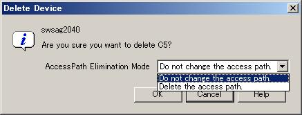
Click [OK] button to continue unregistration.
When the dialog shown below appears, access path settings of the selected CA or HBA (FC adapter) can be deleted. For example, if a CA or HBA (FC adapter) is removed, switch zoning and storage affinity settings of the CA or HBA (FC adapter) are not required. This software product can automatically delete such unnecessary security settings. For the device to be deleted, all of these settings registered with this software product are deleted by selecting "Delete the access path" from "Access Path Elimination Mode" in this dialog. However, such device settings are usually not deleted. If access path settings must be kept because you want to continue operation outside management of this software product, select "Do not change the access path".
Wallpaper function
The following file created as a JPG file can be used as wallpaper for the map view of the GUI window Main view (when the entire configuration is displayed).
The client must be restarted to reflect the wallpaper.
Client install directory:
Client\eclipse\plugins\com.fujitsu.systemwalker.rcnr.client_x.x.x\icons\san_backimage.jpg
(x.x.x will be different depending on the product version.)
This window displays correlation configurations in detail for a device. The Correlation window can display physical configurations such as FC cable connections between devices as lines between devices. It can also display logical configurations such as Logical Volume and RAID Group as elements (explained in a subsequent section).
The Correlation window can be invoked in one of the following three manners.
Clicking [File]-[Correlation Window] from the menu bar
Double-clicking the device framed in black in the Side view
Selecting the device in the Main view, Domain view or SAN View and executing [To Send]-[Correlation Window] on the popup menu
The following explains how to view detail information on devices invoking the Correlation window.
Select [File]-[Correlation Window] from a view of the resource view or select [Correlation Window] in the pop-up menu of the Main view, Domain view or SAN View. The Correlation window as shown on the lower right is then displayed.

Dragging a device icon from the Main view, Domain view or SAN View and dropping it on the Correlation window displays detailed information of the selected device in the Correlation window.
However, Fibre Channel switches, hubs, routers, and ports cannot be dropped on the Correlation window.
When the icon of a device is double-clicked in the Main view, Domain view or SAN view, the Side view of that device is displayed. In the Side view, the frame of the device selected in the Domain view or SAN view is displayed in black. The device with this black frame is to be the currently selected device. When the device with the black frame is double-clicked in the Side view, the Correlation window opens to display details of that device. At this point, the double-clicked device is displayed by selecting [Change Detail View]-[ON]. If the Correlation window has already been opened, details of the device are additionally displayed in that window. When a device with no black frame is double-clicked in the Side view, the Side view of that device opens to display that device with a black frame. Fibre Channel switches, hubs, routers, and boards are not displayed in the Correlation window. The following illustrates the flow of windows switched with double-click.
Several device icons can be selected in the Main view, Domain view or SAN view and dragged in the window. A device icon can be also dragged to an existing Correlation window to add the device to it.
Click the icon of a device in the Main view, Domain view or SAN View to display the popup menu. By executing [To Send]-[Correlation Window], the Correlation window is started and the detail information on the device is displayed in the Correlation window. The selected device is displayed by selecting [Change Detail View]-[ON]. When the Correlation window is already active, the detail information on the device is added and displayed in the current Correlation window. However, Fibre Channel Switches, hubs, routers and ports can not be displayed on the Correlation window. The following flowchart illustrates the procedure after [To Send]-[Correlation Window] is executed.
When the Correlation window starts up, the dialog box below appears. Select a display method and location where to acquire information, and then click the [OK] button.
The amount of detailed correlation information depends on the configuration used, so several minutes may be required to obtain detailed correlation information. In particular, it takes a long time to obtain detailed correlation information from a real device. However, once obtained, detailed correlation information is stored on the admin server. If [a management server] is selected as the information acquisition place in this dialog for the next time the Correlation window is opened, correlation information is displayed relatively quickly, based on the information stored on the admin server instead of that on a real device.
Moreover, the relating device is not able to be displayed by selecting [Only equipment is displayed] in the method of the display in this dialog. To check the latest system device status in the Correlation window opened with this state, select [View]-[Refresh] from the Correlation window menu.
The admin server does not have data when the Correlation window is first opened. Therefore, at this time, information is obtained from real device regardless of the selection (management server or system equipment).
To display the Correlation window, drag & drop the device to the Correlation Window, double-click the device icon on the Side view, or right click the device icon then select [To Send]-[Correlation Window] to select [Change Detail View]-[ON].

Selecting [New creation] from [File] in the Correlation window clears the client window device data displayed in the Correlation window.
In the Correlation window, you can move icons easily. After operations in the Correlation window, you can return the window to the default display by using [View]-[Zoom]-[Fit] or [View]-[Layout]. (For details, see "B.8.1 Screen description".)
Also, the UnknownFC port is displayed as one device.
Note that devices such as internal bridge devices are displayed as externally independent devices of devices such as the LT120 and LT130.
Selecting a device icon and then selecting [Element]-[Detail]-[Expand] in the Correlation window displays detailed information about the selected icon. Alternatively, selecting [Detail] from the popup menu of a selected icon displays the same detailed information. The window below shows detailed information of devices in the server node. The detailed items of devices displayed in the window are called elements.
To return the display from detailed information to the original device icon, select the frame of the device, and then select [Element]-[Detail]-[Collapse] in the Correlation window; select [Detail]-[Collapse] from the popup menu, or double-click the frame of the device.
Select [Select] from the toolbar and double-clicking an area without an element (in the above figure, pale blue portion of [Inside Frame] for a device) displays the selected devices in the full Correlation window, shown as below.

To display the original window, double-click an area without an element in the window.
Displaying details (detail information) of device icons makes the Correlation window seem complicated because the number of elements becomes very large. For this reason, this software product supports the show element function (see "6.2.7 Show element", for details) and element integration function (see "6.2.8 Element integration", for details) for a clearer window. These functions are as follows:
Each device icon and each element icon in the Correlation window indicates the status of a device or element, as described in the table below.
|
Icon state |
Color of icon frame |
Icon |
Description |
Action to be taken |
|---|---|---|---|---|
|
normal |
Transparent or green |
|
The device is operating normally. |
None |
|
warning |
Yellow |
|
An warning-level error was detected on the device. The degraded level differs depending on the unit type and element type. For details, see "B.7 Resource View Properties". |
Replace the faulty part, and execute recovery processing. However, if a middleware element on the server node is faulty, recover it while referring to the general description of the respective product. ->8.1 Windows Displayed in the Event of a Fault and Troubleshooting |
|
error |
Red |
|
An error was detected on the device. The degraded level differs depending on the unit type and element type. For details, see "B.7 Resource View Properties". |
Replace the faulty part, and execute recovery processing. However, if a middleware element on the server node is faulty, recover it while referring to the general description of the respective product. ->8.1 Windows Displayed in the Event of a Fault and Troubleshooting |
|
stop |
Green |
|
The resource is stopped and not available. |
None |
|
fatal |
Red |
|
An error occurred in this resource, and the resource is not available. |
None |
|
unknown |
Grey |
|
The status cannot be obtained. |
None |
|
timeout |
Gray |
|
The device is registered with this software but cannot be recognized by the software. The device properties displayed by the GUI contain the values retrieved the last time the device was recognized. If a Fibre Channel switch enters this state, the GUI does not display any Fibre Channel physical line under control of the Fibre Channel switch. In addition, the software product does not recognize any access path using this Fibre Channel switch. Accordingly, the GUI indicates errors for all such access paths. |
The power supply of the device may be off, or Agent may not be operating, or a LAN error may have occurred. If you changed the IP addresses manually, also refer to "9.1.2 Changing the operating environment" and perform operations to reflect the changes of the IP addresses. If the device uses the SNMP protocol for communication, the community name of the device may differ between the target device and admin server. If the community name of the target device has been changed, set the community name by referring to "D.2 sanma.conf Parameter", and reflect the setting file on this software product. ->Check the device status, and from the [View] menu, select [Refresh Window]. |
|
undefined |
Violet |
|
The unit (device) is undefined in this software product. |
Define the unit (device) in the resource view. |
Detailed information about each element can be displayed in the Properties dialog. The storage system status can easily be determined because the Properties dialog can be displayed for all elements. In the examples shown below, the MultiPath Drive element and ETERNUS3000 RAID Group element are selected for the Properties dialog.
After selecting an element to display detail information, select [Property] from the popup menu or double-click the element.
Each property value is explained in "B.9 Correlation Window Properties".

You can determine the current statuses of the access path and multipath from their colors.
For access path status display, see "6.3.2.4 Access path status display".
The multipath status is displayed as follows:
|
Multipath status |
Color |
Description |
Action to be taken |
|---|---|---|---|
|
normal |
Black |
The multipath is operating. |
None |
|
warning |
Yellow |
The multipath is stopped or is not operating under multipath management. |
If the multipath is in this status, use of one of the access paths making up this path results in an error. Take appropriate action for the access path error according to "8.1 Windows Displayed in the Event of a Fault and Troubleshooting". |
Agent cannot recognize user business processes running separately and other applications operating on a server. For this reason, this software product supports a function that enables applications to be created manually. Application elements are elements displayed in the Correlation window.
You can manually create application elements and associate them with DBMS (Data Base), file system, and raw device, etc. You can also select several elements and register an application. Select the elements that you want to associate, and then select [Creation]-[Create application] from the popup menu. The following Creating Application dialog appears:

For Name of Application, specify an application name related to the selected element (required).
For Administrator information, specify a manager name for this application (optional). The specified manager name is reflected in property manager information about the element.
For Control URL, specify the URL for starting Management Software of this application or a command execution method (optional).
For Memo information, enter memo information (optional). The memo information entered here is reflected in element property memo information.
These settings (except Name of Application) can be changed with the change button which exists in the property of the application element.

You can delete a registered application. Select the application to have to be deleted, and then select [Delete]-[Delete application] on the popup menu.
You can also add a link between an application and an element. Dragging the element and dropping it on the application displays the dialog shown below. Selecting [OK] in this dialog adds a link between the application and element.
Conversely, to delete the link between an application and an element, select the link, and then select [Delete]-[Related deletion with an application] from the popup menu. You can delete several links from the same application.
If information about associated elements (e.g., DBMS (database) or file system) cannot be obtained when reread information is registered after application registration, the application icon is displayed in the warning color. Each element that uses old database information and cannot obtain the current information is displayed in gray.
In such cases, check for why the information could not be obtained (e.g., whether DBMS is operating normally and whether the file system configuration of the server node containing access paths and other configurations are correct). The elements of this status can be associated with the application.
If an element is unnecessary because of a change in operation or other reason, delete the link to it or the related application.
If an admin server name or an IP address is changed, application information is not inherited. In such cases, register the application element again.
By clicking the Route Search Execution icon on the toolbar on the Correlation window while selecting a device icon or element, this displays all of the correlated device icons, element icons, and links in distinct colors. A device icon or element selected is displayed in different colors from the corelated device icons, element icons, and link. Clicking the Route Search Clearance icon on the on the toolbar clears the route. The following shows examples of the operation:

The upper figure above shows a Correlation window displayed after the Route Search Execution icon on the toolbar is clicked. The lower figure above shows a Correlation window displayed after the Route Search Clearance icon on the toolbar is clicked. Even if the device icon display is changed to the device detailed information display, an integration icon is changed to a table element, or a layer is added with the show element function, the display of the route can be kept up. The following shows examples of operation.
The upper figure above shows a Correlation window displayed after a table is selected from table elements for Logical Volume of storage and the Route Search Execution icon on the toolbar is clicked. The lower figure above shows a Correlation window displayed after an LUN integration icon of storage is displayed as a table element. As shown in the figure, since route search is still effective, simply expanding the LUN integration icon into a table element provides information on LUN correlations. The following explains these features using some operation examples.
[Check all the disk related to a certain application]
To determine the disk and storage that contains the disk area used by the application, select the application and click the Route Search Execution icon from the toolbar in the Correlation window. A window opens to show the related element icons and links in the colors shown below. You can now easily determine which disk of which storage is being used.
In a Linux server node equipped with PG-FC 105 (driver version V4.20q.1), PG-FC 106 (driver version V4.20q.1), PG-FCD101 or PG-FCD102, you cannot determine the disk areas that are used by the application because routes beyond the HBA port cannot be searched.
[Checking the multipath configuration]
To determine a multi-path configuration, select a multi-path driver element and click the Route Search Execution icon from the toolbar in the Correlation window. A window opens to show the related element icons and links in the colors shown below. You can now easily determine which path and route are being used.
In a Linux server node equipped with PG-FC 105 (driver version V4.20q.1), PG-FC 106 (driver version V4.20q.1), PG-FCD101 or PG-FCD102, you cannot determine the multi-path configuration beyond the HBA port because routes beyond the HBA port cannot be searched.
[Check all the applications related to a certain disk]
To determine the application of the server node using the disk, select a disk element and click the Route Search Execution icon from the toolbar in the Correlation window. A window opens to show the related element icons and links in the colors shown below. You can now easily determine which application of which server node uses the disk.
In a Linux server node equipped with PG-FC 105 (driver version V4.20q.1), PG-FC 106 (driver version V4.20q.1), PG-FCD101 or PG-FCD102, you cannot determine which application uses the disk because routes beyond the HBA port cannot be searched.
When AffinityGroups are linked to ETERNUS8000, ETERNUS6000, ETERNUS4000 or ETERNUS2000, the AffinityGroup not used is not subject to a route search. Thus, the element icon of the AffinityGroup not used is not displayed in color. If a route search is executed by selecting the element icon of the AffinityGroup not used, only the specified icon is displayed in color.
The End to End list is displayed at the bottom of the Correlation window when selecting [View]-[List(E)] from the menu bar of Correlation window. The End to End list dislays the list of correlated element. When the check on [View]-[List(E)] from the menu bar of the Correlation window is removed, the End to End list becomes non-display. Default is non-display.
The display form of the list is different according to connected pattern of the access path. Therefore, select the tab to switch the display of End to End list. Connected pattern which can be displayed is as follows:
Access path connection between a HBA port and a CA port
Access path connection between a HBA port and other HBA port
Access path connection between a CA port and other CA port
Access path connection between a HBA port and a UnknownFC port
Access path connection between a CA port and a UnknownFC port
Access path connection between a Unknown port and other UnknownFC port
The tab of the list isn't display when the list does not exist. Moreover, End to End list isn't displayed when the all lists don't exist even if the [View]-[List(E)] menu is checked. [List(E)] menu of the menu bar is displayed in the gray.
Figure below is the End to End list of the system which connects the access path between the HBA port and the CA port and between the HBA port and the UnknownFC port. It is the example of the display when the tab between the HBA port and the CA port is selected.
Selecting [File]-[CSV preservation of a list] from the menu bar in the Correlation window saves the End to End list in a CSV file.
Selecting [Visible] from the header pop-up menu provides ON/OFF check boxes to turn visibility of items in the End to End list on or off. The [Kind of Access Path] item cannot be hidden.
Displaying details (detail information) of device icons makes the Correlation window seem complicated because the number of elements becomes very large. For this reason, this software product supports the show element function that provides a clearer Correlation window.
The show element function specifies whether to display the elements on each layer. Select [Element]-[Visible(H)] from the menu bar in the Correlation window, or select [Visible] from the popup menu. The dialog box shown below on the left appears. In the dialog box, select the elements to be displayed. The following dialog box has the default displayed element settings when the server node is selected. All check boxes except those of MultiPath Driver (Slice) and Raw Device (Slice) are selected. The Correlation window displayed at this time is as shown below on the right.
AS shown below on the left, removing the check of check boxes of File System and Mirror Driver layers hides the selected layers as shown below on the right.
Likewise, you can check and uncheck any check boxes in the Show and Hide dialog to adjust the elements displayed in the window. Check box selection is disabled in cases where the minimum amount of information, such as an HBA (port) data, is displayed as required; and in such cases, the contents displayed cannot be controlled.
Settings of this check box are saved to the client. When all the same kind of Unit is selected in Reflection in the dialog of Layer Property, the settings are reflected in all the same kind of units. When only this Unit is selected, the settings are reflected only in the unit currently selected. It classifies it as homogeneous Units is sorted by OS for the seven node and by product name for the storage.
Element integration icons are bigger than other icons. To distinguish element integration icons from other icons, a positive sign (+) is added to the upper left of element integration icons.
The integrated elements can be displayed as the following table (table element) when selecting [Table Element]-[ON] from the popup menu while selecting the element integration icon or double clicking the element integration icon.
By integrating elements, more easily viewable screen can be displayed. However, this setting is not saved. The element integration icon is displayed when the Correlation window is reactivated.
To return the table element, to the element integration icon, select [Table Element]-[OFF] from pop up menu while selecting the table element.
Select the element integration icon which wants to be displayed and select [Property] from pop up menu to display detailed information on each element. For information about each property, see "B.9 Correlation Window Properties". The following example is properties of DBMS Files (Oracle).
To correlate the element in the element integration icon with the application, first, execute the operation to display the element integration icon as the table element. Next, select the elements (element table) that first make are to be correlated as follows and select [Creation]-[Create application] from pop up menu. It is also possible to select two or more tables as shown in figure below.
To display the correlation between the application and the table element is, click the application whose correlation is to be displayed and click the Route Search Execution icon from the toolbar, and the correlating table is displayed in the color. For information about route search, see "6.2.5 Route search".
To search the route of the element in the element integration icon, first, execute the operation to display the element integration icon as the table element. Next, click the [Route Search Execution] icon from the toolbar. Then, when selecting the element which wants to be displayed from the table, the correlated elements are displayed in the color.
When searching the route, the color of the correlated table, which is in the table element, is changed when the element integration icon is displayed as the table element. Which element correlates can be easily recognized.
When large-scale configuration storage such as ETERNUS8000, ETERNUS6000 or ETERNUS4000 is displayed on the Correlation window, the Correlation window can look complicated though it depends on the model and the configuration. For that reason RAID Group Integration function is supported as a function to make the screen look simple. By using this function, the number of the displayed element can be decreased and the display time for the Correlation window can be shortened. If the large-scale configuration storage exists in the system, it is suggested that RAID Group integration mode should be switched on.
The client definition file is stored in the following.
Correlation window
|
Client install path \Client\eclipse\plugins\com.fujitsu.systemwalker.rcnr.client_x.x.x\Client\etc\san\gui\groupmode.dat |
When Correlation window started
|
Client install path\Client\etc\san\gui\groupmode.dat |
By changing the value of this definition file, RAID Group integration mode (on/off) can be switched.
GROUPMODE_ETERNUS=0
Set integration mode of RAID Group element to "OFF" (default).
GROUPMODE_ETERNUS=1
Set integration mode of RAID Group element to "ON".
The following figures show the Correlation windows in case that RAID Group integration setting parameter is OFF and ON, respectively:
This is a function that can display the location of disk allocation of storage. Select the storage which has to be displayed and select [Element]-[Action]-[Disk Map] from the menu bar. The following disk allocation is displayed:
GR740, ETERNUS3000, ETERNUS4000, ETERNUS6000 and ETERNUS8000 may be offered in a format that one case is equipped with several racks. To make it clear how disks are deployed on respective racks, information is displayed on each tab by rack. Selecting the tab of a rack you want to view displays disk information corresponding to the rack.
The device name indicates the name of a selected storage device.
Assigned disk information indicates the number of disks assigned to RAIDGroups. System disks (displayed as system) are classified as assigned disks. Hot spares are classified as assigned disks with disk icons displayed as HS. A common RAIDGroup is identified in the same color. The disk locations can easily be recognized on this window. Unassigned disk information indicates the number of disks mounted on the storage but not assigned to RAIDGroups. A disk icon displayed in white represents an unassigned disk.
The total number is the sum of assigned and unassigned disks. The locations of disks that are not mounted on the storage are indicated with disk icons in gray.
Groups in RAID information indicate RAID groups. Levels indicate the RAID levels of the corresponding RAID groups, the number indicates the number of disks making up the corresponding RAID group, the color schemes indicates the corresponding RAID groups. The disk arrangement corresponds to the actual device deployment. Slots are deployed from the left to right for GR series and from the right to left for ETERNUS series. DE-ID on the left indicates the drive enclosure ID.
If a disk fails, the frame of that disk is displayed in red. If this disk is alternated with a hot spare, the hot spare is displayed in the assigned color. Placing a mouse on a failed disk brings up the detailed error information.
The RAID group information and disk arrangement windows correlate with each other. Selecting a RAID group in RAID group information causes that the disks related to the RAID group are displayed in distinct colors on the disk arrangement window. Selecting a disk on the disk arrangement window causes that all disks in the RAID group configuring the disk and the RAID group in RAID information are displayed in distinct colors as well. When a selected RAID group belongs to a rack currently hidden, tabs for the related disks are displayed.
The initialization of the Correlation window is shown below. The End to End list is a initial display when the access path between HBA port and CA ports is connected.
|
Element name |
End to End list |
Show element |
Element integration |
Description |
|---|---|---|---|---|
|
Business (Application) |
Yes |
Yes |
- |
Indicates an application. This element can be created manually. |
|
DBMS (Data Base) |
Yes |
Yes |
Yes |
Indicates a database unit. |
|
DBMS (File type) |
Yes |
Yes |
Yes |
Indicates a database file type. |
|
DBMS (File System) |
Yes |
Yes |
Yes |
Indicates a database file. |
|
File System (Mount Point) |
Yes |
Yes |
- |
Indicates the mount point of the file system. |
|
File System (Domain) |
Yes |
Yes |
Yes |
Indicates the space (area) used by the file system. |
|
Mirror Driver (Volume) |
Yes |
Yes |
Yes |
Indicates a mirror disk volume. |
|
Mirror Driver (Group) |
Yes |
Yes |
- |
Indicates a mirror disk group. |
|
Mirror Driver (Disk) |
Yes |
Yes |
- |
Indicates a mirror disk. |
|
Mirror Driver (Class) |
- |
Yes |
- |
Indicates a mirror disk class. |
|
Multipath Driver (Slice) |
Yes |
- |
- |
Indicates a multipath slice. |
|
Multipath Driver (Disk) |
Yes |
Yes |
Yes |
Indicates a multipath disk. |
|
Raw Device (Slice) |
Yes |
- |
- |
Indicates a Raw device slice. However, only the slices used from DBMS, File System, Mirror Driver, and MultiPath Driver are displayed. |
|
Raw Device (Disk) |
Yes |
Yes |
Yes |
Indicates the Raw device disk of storage connected from an HBA. |
|
HBA |
Yes |
Yes |
- |
Indicates the FC-HBA card of a server node. |
|
HBA (Port) |
Yes |
Yes |
- |
Indicates the port installed in an FC-HBA card. |
|
Switch (Port) |
Yes |
Yes |
- |
Indicates a Fibre Channel switch port. |
|
CA (Port) |
Yes |
Yes |
- |
Indicates the port where a storage channel adapter is installed. |
|
CA |
Yes |
Yes |
- |
Indicates a storage channel adapter. |
|
CM |
Yes |
Yes |
- |
Indicates a storage controller. |
|
IOB |
- |
Yes |
- |
Indicates a storage IF unit. |
|
Router |
- |
Yes |
- |
Indicates a storage router. |
|
DA |
- |
Yes |
- |
Indicates a storage device adapter. |
|
Affinity Group (also called ZONE) |
Yes |
Yes |
- |
Indicates a storage affinity group (= zone). |
|
LUN (=LUNV,OLU) |
Yes |
Yes |
Yes |
Indicates the LUN number of a logical volume defined in a storage affinity group (= zone). |
|
Logical Volume |
Yes |
Yes |
Yes |
Indicates a logical volume (= LUNV,OLU) of storage. |
|
RAID Group |
Yes |
Yes |
- |
Indicates a RAID unit of storage. |
|
Disk |
Yes |
Yes |
Yes |
Indicates a single disk unit of storage. |
|
DE |
- |
- |
- |
Indicates a storage disk enclosure. |
|
Battery |
- |
- |
- |
Indicates a storage battery. |
File handling
Selecting each menu in [File] from the Correlation window menu bar enables you to read the configuration data displayed in the Correlation window from a file and save the data to a file.
|
Menu command name |
Description |
|---|---|
|
Open |
Reads and displays configuration data. The data displayed in the current Correlation window is cleared. |
|
Save |
Saves the configuration data displayed in the current Correlation window to the currently specified file. |
|
Save As |
Saves the configuration data displayed in the current correlation window in a *.ccw file with a new name. |
|
CSV preservation of a list |
Saves the contents displayed on the End to End list to the specified file in the CSV format. Other applications can use the saved contents because the contents are in the CSV format. |
Selecting [File]-[Print] from the Correlation window menu bar enables the Topology map (frame where the device is displayed) to be printed in the format specified in Page Setup.
As for the size of the form and the layout when printing, a specified value in [Page Setup] is given to priority.
Page Setup
Selecting [File]-[Page Setup] from the Correlation window menu bar displays the following dialog in which you can set a page format for printing:
(Print range)
Print Entire Graph
Prints all objects (including undisplayed objects) on the Topology map.
Print Current Window
Prints only the objects displayed on the Topology map.
Print Current Selection
Prints only the objects currently selected on the Topology map.
[Scale By] (Scaling)
Pages
Prints the map on pages measuring "Page Columns (horizontal) x Page Rows (vertical)".
Note: The map is not printed if 0 is specified for Page Columns and Page Rows.
Actual Size
Prints the map with the default icon size as a reference.
Note: The map is not printed if 0 is specified for Page Columns and Page Rows.
Zoom Level
Prints the map in the currently displayed size.
Note: The map is not printed if 0 is specified for Page Columns and Page Rows.
[Caption] (Title)
Print Caption
Adds the title displayed in the text area.
Font...
Sets the title font.
Note: If the dialog is closed and then opened again after the font has been changed, the font setting is reflected in the text area.
Position
Sets the title position.
[Margins(Inches)] (Margin)
[Multipage Printing] (Setting for printing multiple pages)
Print Page Numbers
Prints the page and the coordinates at which the page is located on the map.
Print Crop Marks
Prints the page including only the edges and border lines of adjacent pages, if they are contained in the screen.
[Other] (Others)
Print Border
Prints the page including the page margin and the border lines of adjacent pages between screens.
Color...
Specifies a border line color.
Print Background
Prints the background. (Unsupported)
Print Grid
Prints ruled lines. (Unsupported)
(Lower button)
Default
The setting of this "Page Setup" dialog is returned to default.
Page Setup...
A common page setting dialog to Windows is displayed.
Overview
Selecting [View]-[Overview(S)] from the Correlation window menu bar displays the Overview. The Overview displays the whole correlation structure in the window. The Overview linked with the Correlation window. The red frame in the Overview indicates the range of display in the active Correlation window. When the red frame in the Overview is moved, the range of display in the Correlation window is moved accordingly. In addition, when the red frame of the overview is scaled, the range of display in the Correlation window is scaled accordingly.
Marquee
Marquee is used to display only the portion selected in the Correlation window. By selecting [Marquee] on the Correlation window toolbar and specifying the range of display, you can display the selected portion in the entire Correlation window. In the following figure, the range of display of the selected portion is specified with the toolbar Marquee icon selected. However, when the mouse cursor is moved to the table element, it is changed from the [Marquee] to the [Select]. Move the mouse cursor to other than the table element, and select the range again.
As shown in the following figure, the portion within the specified range is displayed in the entire Correlation window:
InteractiveZoom
To magnify or reduce the display in the Correlation window, use InteractiveZoom together with the mouse. To magnify the display in the Correlation window, select [InteractiveZoom] on the Correlation window toolbar, and move the mouse down while holding down the left mouse button. Moving the mouse up reduces the display in the Correlation window. The following figure shows magnified and reduced displays in the window. However, when the mouse cursor other than the table element, it is changed from the [InteractiveZoom] to the [Select]. Move the mouse cursor other than the table element.
Call management software
The Management Software for each element can be invoked from the Correlation window. In each property, the Management Software is displayed as follows.
Clicking the URL displayed for "Management Software" displays related Management Software as shown in the following figure:
Layout
Device icons and element icons can be displayed with different layout logic (algorithms). To use the function, select a layout icon on the toolbar.
The hierarchical layout (Hierarchical) is usually selected. Selecting other layouts, however, enables you to check the relationship between devices from different perspectives.
|
Layout name |
Toolbar display |
Display example |
|---|---|---|
|
Hierarchical (Default) |
|
|
|
Circular |
|
|
|
Orthogonal |
|
|
|
Tree |
|
|
|
Symmetric |
|
|
Orthogonal Line Mode
The element arrangement is displayed by orthogonal line mode when selecting [View]-[Orthogonal Line Mode] from the menu bar of the Correlation window, and the display of the portrait can be shortened. The window displayed in orthogonal line mode is displayed as follows. However, the orthogonal line is not displayed between device icons.
Table Element Display Magnification Setting
When [Table Element Magnification] of [Element] is selected from the menu bar of the Correlation window, the dialog of the table element display magnification setting is displayed. The magnification to which the table element is displayed can be set in this dialog. The display magnification which can be set to the range 1-100. All the table elements displayed in the Correlation window are displayed at the set display magnification.
Moreover, the default of the display magnification is twice. The display magnification set in this dialog is saved in the client. Even if the display magnification of the table element is enlarged, the screen size does not grow. Therefore, even if the display magnification of the table element is enlarged more than a current value, the table element might seem not to be displayed greatly. However, the element icon and an integrated element icons other than the table element are actually displayed small.
Correlation Window Unit Start
In the Correlation window, the function (SaveAs) to save the composition data displayed in a present Correlation window in the file and the function (Open) to read this composition data and display is supported. The saved composition data can be displayed on the window of the client which exists in another place by using this function. However, when the administrative client which exists in another place is not connected with the admin server, the saved composition data cannot be displayed on the window. Therefore, a Correlation window unit start is supported in this software product.
When saved composition data (CCW file) is double-clicked, the Correlation window is started. This operation becomes the same operation as the selection of the file from the Correlation window by selecting [Open] of [File] menu.
If one Correlation window is opened to display the composition data stored in a file and another Correlation window is opened to display different composition data before retrieval of the composition data for the first window is completed, the first Correlation window may freeze. Do not open more than one Correlation window at the same time to display composition data. If the Correlation window freezes, forcibly close the window by using the task manager. Then, perform Correlation window unit start again.
In this software product, the logical paths of server node and storage devices are defined as access paths.
Access paths are generated by the following access control functions of the server node, Fibre Channel switch, and storage.
Fibre Channel adapter manufacturers provide host storage affinity. To set the definition of a channel adapter (CA) that can be accessed and the ID of the corresponding server node side, write the world wide port name (WWPN) used by Fibre Channel for the CA on the storage side, in the definition file. Host storage affinity is also called LUN mapping or WWPN binding. This software product refers to this function as storage affinity. Define the settings of this function in definition files such as /kernel/drv/sd.conf and /kernel/drv/fjpfca.conf (PW008FC2A, PW008FC2-G, PW008FC3, GP7B8FC1A, GP7B8FC1-G, GP7B8FC1, SE0X7F11F, SE0X7F12F), /kernel/drv/sd.conf (SN10-FC01, JNI), /kernel/drv/lpfc.conf, or lpfs.conf (LP-9000, 9002S, 9002L, 9802, 10000).
Solaris OS environment HBAs supported in this product all support this function (except XSEFC401AF, XSEFC402AF, SG-XPCI1FC-QF2, SG-XPCI2FC-QF2, SG-XPCI1FC-QL2 and SG-XPCI2FC-QF2-Z , which do not). Windows/Linux/HP-UX environment HBAs do not support this function, however. To collect the information described above, Agent must be installed.Switch manufacturers provide Fibre Channel switch zoning. Information such as the WWN/port number used by Fibre Channel for the host bus adapter (HBA) on the server node side and the WWN/port number of channel adapters (CAs) on the storage side is combined in a zone unit, and access from ports other than the port defined for the zone are restricted.
Storage manufacturers provide storage host affinity. The storage side recognizes the WWPN of the HBA on the server node side in order to restrict access. Associations of WWPNs of HBAs with storage areas(AffinityGroup/Zone) can also be set. ETERNUS8000, ETERNUS6000, ETERNUS4000 and ETERNUS2000 refer to storage host affinity as Set Affinity Group, Set Host-Affinity Group, ETERNUS4000 (M80,M100), ETERNUS3000/GR refers to storage host affinity as Host Table Settings, zone definition, on host affinity.
This software product integrates and manages these functions to facilitate definition of settings that make use of the characteristics of SAN security and each function.
This software product currently supports storage affinity only for the Solaris OS server node and host affinity only for the ETERNUS8000, ETERNUS6000, ETERNUS4000, ETERNUS3000, ETERNUS2000 and GR series. An increase in the number of devices supported by this software product is scheduled. Without using storage affinity and host affinity, it can control access paths only by using the zoning function of Fibre Channel switches. It controls access paths according to the functions and settings of individual devices.
This software product gathers information from each device and displays the status of access paths or the status of logical access paths from the server node. This function is effective for verifying the validity of system configuration setup and recognizing the effect of a resource error because it enables the logical relationship in the more complicated SAN environment to be easily determined.
In the Solaris OS versions, only PW008FC2A, PW008FC2-G, PW008FC3, GP7B8FC1A, GP7B8FC1-G, GP7B8FC1, SE0X7F11F and SE0X7F12F can display access paths with FC-AL connections. In the Windows versions, only Fujitsu GP5-FC102, PG-FC102, PG-FCD101, PG-FCD102 and Qlogic HBAs can display access paths. If the server node operates under the Solaris OS and the storage system is a library, tape, or bridge device, only the following tape driver can display access paths:
st, ftla, fsct, IBMtape, mt, lb, sg.
The Server Node view and Storage view can be used to check access path display. In each view, enable access path display from the [View] menu. Physical paths are displayed in black, and access paths are displayed in blue, yellow, or red.

Clicking an HBA displays in light blue all access paths managed by the HBA and the area allocated to the HBA for storage (for the ETERNUS8000, ETERNUS6000, ETERNUS4000, ETERNUS3000, ETERNUS2000 and GR series, items up to the Affinity Group (zone) number are displayed).
To determine which device file in the server node is associated with one of these displayed access paths, check "Properties" of the HBA, or open an access path dialog box from the list in "Access Path Information" shown in the following figure.
If the Solaris OS device file is cxtyd*s*, for example, the control number is x and the target ID of access path information is y in HBA "Property". (If the HBA is XSEFC401AF, XSEFC402AF, SG-XPCI1FC-QF2,SG-XPCI2FC-QF2,SG-XPCI1FC-QL2 or SG-XPCI2FC-QF2-Z, however, the controller number, target ID, and LUN cannot be displayed.) In the following figure, the correlation of device files c2t0d0 to c2t0d15 can be recognized because the controller number of the selected HBA is 2, the target ID is 0, and LUN is 0-15.

Also, you can determine the target ID and LUN by selecting [Property] on the popup menu. (If the HBA is XSEFC401AF, XSEFC402AF, SG-XPCI1FC-QF2, SG-XPCI2FC-QF2, SG-XPCI1FC-QL2 or SG-XPCI2FC-QF2-Z, however, the target ID and LUN cannot be displayed.) As shown in the figure below, the popup menu is displayed by clicking and then right-clicking on an access path. In "Property", "Error Description" can be displayed. The reason for the abnormal access path is written in "Error Description". (No reason may be partially written.)
Clicking on a selected access path displays in light blue the physical paths constituting the access path, as shown in the figure below. However, if several Fibre Channel switches in the access path are cascaded, intermediate paths between the Fibre Channel switches cannot be displayed.
When the Fujitsu multipath disk control mechanism is used in Solaris OS, Windows or Linux environment, the device file name of the multipath disk mechanism is displayed on the server node. In Solaris OS, Windows (In case of SSC agent, only using the HBA produced by QLOGIC Co.), and Linux (unless the HBA is PG-FC105 (driver version:V4.20q-1), PG-FC106 (driver version:V4.20q-1), PG-FCD101, or PG-FCD102) environments, it is possible to display the access path that configures the device file and the storage area information in turquoise by left-clicking this device file name to select it. With this function, you can visually determine the relationship between storage media and the device files in the server node, so the function improves the efficiency of storage system operation management.
With only the side view displayed, the FcHba-FcHba (or FcCa-FcCa) access path is not displayed. When FcHba (or FcCa) with the FcHba-FcHba (or FcCa-FcCa) access path is clicked, the access path destination FcHba (or FcCa) and its access path are highlighted.
Clicking a channel adapter (FC port) of a storage system where access paths are created displays in light blue all access paths and HBAs managed by the channel adapter.
By left-clicking the representation of the storage area (Affinity Group (zone)/indicated as the colum in the figure), all access paths and HBAs that are managed by the related CA are displayed in blue. In Solaris OS, Windows (In case of SSC agent, only using HBA by QLOGIC Co.) and Linux (only using HBA except for PG-FC105 (driver version:V4.20q-1), PG-FC106 (driver version:V4.20q-1), PG-FCD101, PG-FCD102) environment, if the Fujitsu multipath disk control mechanism is set up, the corresponding device file name is also displayed in light blue.
|
Access path status |
Color |
Description |
Action to be taken |
|
|---|---|---|---|---|
|
OK |
(WWPNBINDING) |
Green |
The access path is normal. If the server node OS is Solaris: Indicates that storage affinity (WWPN binding) has been set in the server node and that the LUN is recognized by the OS, if the HBA is not XSEFC401AF, XSEFC402AF, SG-XPCI1FC-QF2, SG-XPCI2FC-QF2, SG-XPCI1FC-QL2 or SG-XPCI2FC-QF2-Z. If the server node OS is not Solaris: Indicates that the HBA binding type is WWPN. |
None |
|
(ANOTHERBINDING) |
Blue |
The access path is normal. If the server node OS is Solaris: If the HBA is not XSEFC401AF, XSEFC402AF, SG-XPCI1FC-QF2, SG-XPCI2FC-QF2, SG-XPCI1FC-QL2 or SG-XPCI2FC-QF2-Z, indicates that storage affinity (LUN mapping) has not been set in the server node, but that the access path has been set using the Fibre Channel switch zoning information or storage host affinity information. (If the HBA is PW008FC2A, PW008FC2-G, PW008FC3, GP7B8FC1A, GP7B8FC1-G, GP7B8FC1, SE0X7F11F, or SE0X7F12F, and there is a Fibre Channel switch environment, the storage cannot be accessed solely with these settings. The access path for this path must be set. There is no problem with Loop connections.) If the HBA is XSEFC401AF, XSEFC402AF, SG-XPCI1FC-QF2, SG-XPCI2FC-QF2, SG-XPCI1FC-QL2, SG-XPCI2FC-QF2-Z, and the access path status is Normal, the access path color is always Blue. This indicates that the access path is set using either the Fibre Channel switch zoning information or the storage host affinity information. If the server node OS is not Solaris: Indicates that the access path has been set using the Fibre Channel switch zoning information or storage host affinity information, and that the HBA binding type is not WWPN. |
None. However, the LUN cannot be accessed if there is a Fibre Channel switch environment and the HBA is of a type shown in a) or b). Take the action shown indicated below. a) If the HBA is PW008FC2A, PW008FC2-G, PW008FC3, GP7B8FC1A, GP7B8FC1-G, GP7B8FC1, SE0X7F11F, or SE0X7F12F 1) Configure the HBA N-port settings. Refer to "4.1.1.2 N-port settings", and check the N-port settings. If the settings are incorrect, correct them. The N-port settings may be deleted by use of the ETERNUS multipath driver path remove command. 2) Set the access path If the path status does not change to Green after configuring the N-port settings, refer to "6.3.3 Access path setting", select this path, and set the access path. If the HBA is XSEFC401AF or XSEFC402AF, the following action is required to make the LUN be recognized by the OS: 1) Set the HBA N-port(This procedure is a necessary procedure only for the fiber channel switch environment.) Refer to "4.1.1.2 N-port settings", and check the N-port settings. If the settings are incorrect, correct them. 2) Make the OS recognize the LUN Check the storage Ap_id using the cfgadm -al command, and make the OS recognize the LUN using the cfgadm -c configure Ap_id command. For details about the commands, check the man command. When HBAis SG-XPCI1FC-QF2,SG-XPCI2FC-QF2,SG-XPCI1FC-QL2,SG-XPCI2FC-QF2-Z, the following actions are required to make the OS recognize the LUN. 1) Check the storage Ap_id by the cfgadm -al command which makes the OS recognize the LUN and then make the OS recognizes the LUN. Command details can be checked by the man command. |
|
|
Access path error |
Red |
The access path is disconnected due to an error (if the multipath control mechanism is installed). Or Another part failure caused or may have caused an access path error. (This state also occurs if a device in the access path is faulty.) Moreover, this state also occurs when the Fibre Channel cable on a route is disconnected. |
Replace the faulty part, and execute recovery processing. ->8.1 Windows Displayed in the Event of a Fault and Troubleshooting |
|
|
Config miss Match and The access path must be inherited. |
Yellow |
"Yellow" indicates "Config miss Match" or "The access path must be inherited". Right-click the access path, and select [Properties] on the popup menu. Check the access path status. |
|
|
|
"Config miss Match" Access path settings are incorrect. (Example: WWPN binding is set on the server node side but zoning is not set on the Fibre Channel switch side.) Or the access path cannot be confirmed because the Fibre Channel switch is not registered. For example, one possible cause is that the Fibre Channel switch has erroneous zoning information. |
If the Fibre Channel switch is not registered, register it. Right-click the access path, open "Properties" from the popup menu, and check "Error contents". Set or delete the access path as required. |
|||
|
"The access path must be inherited". The access path must be inherited because the HBA has been replaced. |
||||
You can know the reason of the Access Path error or the Config miss Match from the Access Path Properties. (see "B.7.3 Access path properties".)
The Solaris OS server node uses special file /dev/rdsk/cXtX, /dev/rmt to obtain WWPN binding information. For this reason, to recognize WWPN binding, this special file (device file) must be created in advance. If any unused special file is in /dev/rdsk/, /dev/rmt, it causes the access path display to be incorrect. If access path display by this software product differs from that by system equipment, clarify the special files defined in the following operations:
[For Solaris 2.6 OS]
# touch /reconfigure
# /usr/sbin/shutdown -y -i6 -g0 (server node restart processing)
[Solaris 7, 8, 9,10 OS (For the environment which uses hard disk driver (HDDV), and does not use multipath control (ETERNUS/GR Multipath Driver, MPLB, MPHD))]
# touch /reconfigure
# /usr/sbin/shutdown -y -i6 -g0 (server node restart processing)
After the server node has been restarted
# format (Loading processing to HDDV driver's kernel)
# disks -C
[Solaris 7, 8, 9,10 OS (For the environment which uses both hard disk driver (HDDV) and multipath control (ETERNUS/GR Multipath Driver, MPLB, MPHD), or uses neither.)]
# touch /reconfigure
# /usr/sbin/shutdown -y -i6 -g0 (server node restart processing)
After the server node has been restarted
# disks -C
In a storage system where a Fibre Channel switch is between a server node and storage, this software product automatically changes the security settings supported by each device and sets an access path, as shown in the figure below. If no security mechanism is provided on the device side, setting up security may not be possible. However, the security mechanisms of other devices create access paths. If none of the devices constituting these access paths is equipped with a security function, security cannot be set up but the access paths can be accessed from the server node. This software product can set an access path only in the Fibre Channel switch environment.
Even if the access path state is "Config miss Match," you can create a correct access path by setting the access path properly. Select the access path whose state is "Config miss Match" in the Access Path window, and set the access path.
This function can set an access path not only between a server node (HBA) and storage (CA) but also between a server node (HBA) and a bridge port, between two server nodes (HBAs), and between storage systems (CAs).
Each storage system has requirements, such as HBA types used, for guaranteeing operation according to the mutual connection verification status. Set each access path so that these requirements are satisfied. For more information about the requirements, contact the respective storage system distributor.
|
Device type |
Contents set by this software product |
||
|---|---|---|---|
|
Solaris OS server node |
Agent available |
PW008FC2A, |
[Partner device is a disk (excluding a manually embedded disk) unit] Setting of sd.conf LUN / setting for associating fjpfca.conf TID with WWPN [Partner device is a tape, library, bridge, or manually embedded disk] Setting for associating fjpfca.conf TID with WWPN [Partner device is an HBA] No setting |
|
SN10-FC01, |
[Partner device is a disk (excluding a manually embedded disk)] Setting for associating sd.conf TID and LUN with WWPN [Partner device is a tape, library, or HBA] No setting |
||
|
LP-7000, |
[Partner device is a disk (excluding a manually embedded disk)] Setting for associating sd.conf/lpfc.conf or lpfs.conf TID and LUN with WWPN [Partner device is a tape, library, bridge, or manually embedded disk] Setting for associating lpfc.conf or lpfs.conf TID and LUN with WWPN [Partner device is an HBA] No setting |
||
|
QLA-2200 |
[Partner device is a disk (excluding a manually embedded disk)] Setting for associating sd.conf/qla2200.conf TID and LUN with WWPN [Partner device is a tape, library, bridge, or manually embedded disk] Setting for associating qla2200.conf TID and LUN with WWPN [Partner device is an HBA] No setting |
||
|
HBA (other than above cases) |
No setting |
||
|
Agent unavailable |
No setting |
||
|
Windows server node |
Agent available/unavailable |
No setting |
|
|
Linux server node |
Agent available/unavailable |
No setting |
|
|
HP-UX server node |
Agent available/unavailable |
No setting |
|
|
Other server nodes |
Agent unavailable |
No setting |
|
|
Fibre Channel switch |
With zoning setting |
WWPN one-to-one zoning is set. (However, this zoning is not set if the Fibre Channel switch side already has sufficient port zoning.) |
|
|
Without zoning setting |
No setting |
||
|
ETERNUS8000, ETERNUS2000, |
With security setting |
Setting of HBA WWPN for security |
|
|
Host affinity (zone) setting |
Setting of HBA WWPN to the affinity group (zone) |
||
|
Without security setting |
No setting |
||
|
Other storage/tapes/bridges |
No setting |
||
Only the administration account whose authority level is "privileged administrator" can set access paths.
To change the HOST ID (Target ID) of a set access path, delete the path and then set it again with a new ID.
To change the specified AffinityGroup/zone name on the ETERNUS/GR side of a set access path, delete the path and then set it again with a new zone.
From the [View] menu, select [Refresh], and verify that all Fibre Channel switches cascaded to the Fibre Channel switch associated with the access path setting are correctly recognized in the current status. Once an access path is changed because a Fibre Channel switch is temporarily disconnected from the cascade connection, the old cascade connection cannot easily be recovered. (In this event, execute the cfgClear command to delete zoning information for the Fibre Channel temporarily disconnected from the cascade connection. This enables cascade reconnection.)
When an access path is set for an ETERNUS storage device, "Host response" must be set for the storage device according to the environment. For details, refer to the related ETERNUS disk array manual.
Check the following settings on the storage side before setting an access path:
ETERNUS8000 series, ETERNUS6000 series, ETERNUS4000 series, ETERNUS3000 series, ETERNUS2000 series and GR series
By setting up the zone (host affinity) function, you can use storage areas efficiently on a storage area network. To use this zone function, you must set up a zone on the storage side before setting an access path. Set up a Affinity Group/zone with ETERNUSmgr/GRmgr, or consult with your Fujitsu customer engineer.
When setting an access path, an HBA and CA must be physically connected via a Fibre Channel switch.
When HBA and CA are connected via FC hub or in FC-AL one-to-one correspondence, the setting of the access paths is not supported. Set to the server node and storage manually.
Each HBA must be connected to a Fibre Channel switch and operate as the N port or NL public.
All of a Fibre Channel switch on the way of the access path setting, HBAs, server nodes, CAs and storages should be operating normally.
The access path setting function of this software product does not write access path setting information to /kernel/drv/sd.conf in an environment in which the ETERNUS multipath driver is installed. However, the setting information is written to /kernel/drv/fjpfca.conf or /kernel/drv/lpfc.conf.
Therefore, to use the access path setting function of this software product to build a multipath, follow the procedure below.
Install the ETERNUS multipath driver (mpdpkgadd command).
After installation is completed, you are asked whether you want to configure the environment for the multipath driver. Enter "n" to exit.
[Interactive processing example]
------------------------------------------------------------------------------
Do you want to make a multipath configuration now? [y,n,?,q] n
------------------------------------------------------------------------------
Make access path settings by using this software product.
Make access path settings to build a multipath configuration.
The access path setting information with these settings is written to fjpfca.conf or lpfc.conf.
Configure the environment for the multipath driver (grmpdautoconf command).
For details on interactive processing, see the ETERNUS multipath driver manual.
However, if you are asked whether you want to make ETERNUS and switch settings, enter "n" (No & skip).
[Interactive processing example]
------------------------------------------------------------------------------
Do you want to set Host affinity & set a switch zoning?
Yes ---> hit the 'y' key.
No & skip ---> hit the 'n' key.
Quit ---> hit the 'q' key.
Please input [y,n,q]n
------------------------------------------------------------------------------
Do not use this software product to set any access path in a multipath configuration before installing the ETERNUS multipath driver (steps 1 and 2 cannot be reversed). If an access path is thus configured before the ETERNUS multipath driver is installed, the multipath driver has conflicting environmental conditions since setting information is written to sd.conf (an undefined target ID is used in sd.conf).
When the hot system expansion function of a server node is disabled, the access path setting function writes access path information in /kernel/drv/sd.conf on the server node side. For this reason, when using the HDDV and GR Multipath Driver, MPLB, MPHD, set access paths according to the sd.conf rewrite timing specified for environment setup in the respective manuals.
To add a logical unit access path to the host being used with the HDDV or Multipath disk control (ETERNUS Multipath Driver, GR Multipath Driver, MPLB, MPHD), or to set an additional logical unit in the server node, configure with [Set Access Path] the required setting for ETERNUS Multipath Driver, GR Multipath Driver, MPLB, MPHD, HDDV.
If the HDDV version is 2.2 or higher and hot system expansion is enabled by in hddvadm -M, hot system expansion can be implemented for the logical unit in the Solaris 9 OS or in a special environment. Before hot system expansion, specify the hddv.conf editing method and hddvadm -M use method and set up the special environment manually according to the related HDDV manual. (When using hddvadm -M, this software product does not edit files named hddv.conf and sd.conf. Edit these files manually to add definitions separately. It edits the file named fjpfca.conf automatically.)
Do not supposed to execute the grmpdautoconf command of GR Multipath Driver (GR Multipath Driver is 1.0.4 or higher) in the environment that hot system expansion of hddvadm -M is unavailable in Solaris OS server node (Agent is available). The HDDV multipath environment can be automatically constructed as the number of sd.conf TID for Agent setting and the number of hddv.conf TID for GR Multipath Driver setting are doubly defined. If the access path setting is executed in the above environment of this software product, execute HDDV driver multipath disk control construction by using the constructing procedure from sd driver (standard settings). If hot system expansion of hddvadm -M is available in an environment, the grmpdautoconf command can be executed because the definition setting for sd. conf is not performed in the access path setting of this software product.
Set access paths for the Fibre Channel. You can set a new access path and clarify access path settings (correction in the event of an access path setting conflict), and also change settings of logical unit expansion in the access path.
Configure the access path environment by installing additional storage and connecting a Fibre Channel cable, etc.
Preprocessing for the device driver definition file
When ETERNUS Multipath Driver 2.0.1 or higher is used
No preprocessing needs to be performed.
Solaris 8 OS and Solaris 9 OS
This procedure changes the disk array control driver from sd to hddv when the grmpdautocon command is executed in the GR Multipath Driver environment (v1.0.4 or later) or when the hot system expansion function (hddvadmM) is enabled for setting a hard disk driver (hereinafter abbreviated as hddv).
Check whether the hddv configuration information file (hddv.conf) has been created.
# ls /kernel/drv/hddv.conf
If the file is not found, execute the following command and create the hddv.conf file:
# hddvadm -M
When the file is found, check whether the file content is of class or parent type.
(Example)
Example of hddv.conf of the parent type
name="hddv" parent="scsi" target=16 lun=0;
Example of hddv.conf of the class type
name="hddv" class="scsi" target=16 lun=0;
The class type of file requires no preprocessing. (All hddv.conf files created by the hot system expansion command [hddvadm M] are of the class type.)
For the parent type of file, follow the instructions below to initialize the non-hot system expansion environment and move into the hot system expansion environment. To directly use the non-hot system expansion environment, follow the procedure for setting non-hot system expansion (hddvamd m).
Execute hddvadm -i.
Confirm that /kernel/drv/hddv.conf is not present.
Delete the entries made for recognizing the disk array device from the sd configuration information file (sd.conf).
Execute the following command and create an hddv configuration information file (hddv.conf):
# hddvadm -M
Before setting the access path, do not execute the grmpdautoconf command without executing the hddvadm M command that enables the hot system expansion environment. Otherwise, the TargetID of sd.conf and TargetID of hddv.conf of the GR Multipath Driver setting may be defined twice. Consequently, a HDDV multi-path environment may be automatically created due to the duplicated TargetID definition.
In a non-hot system expansion environment, sd.conf is described by "access-path setting". Therefore, the TargetID of sd.conf may match that of hddv.conf, which is edited later. This duplicated TargetID definition must be avoided. In a hot system expansion environment (hddvadm M), sd.conf is not described by "access-path setting". Therefore, the TargetID definition will not be duplicated.
In the MPLB2.0 or MPLB2.1 environment with non-hot system expansion specified (hddvadm -m), the commands for adding and removing paths are not supported. Accordingly, the multipath configuration must be canceled once. Execute the destroy command of #iompadm to cancel the multipath configuration.
In the multipath disk control (GR multipath driver, MPLB, MPHD, or HDDV) environment with non-hot system expansion is specified (hddvadm -m), execute the following command on the target server node:
# hddvadm -i
By executing this hddvadm -i command, hddv.conf file moves to sd.conf and mphd.conf/mplb.conf file is saved. However, in the hot system expansion environment or in the hddvadm -M execution environment, hot system expansion can be performed without executing the hddvadm -i command. Therefore, this command need not be set.
This software product automatically edits sd.conf (in the hot system expansion environment) and the configuration definition files (*.conf) of the target HBA when an access path is being set. Stop all programs affected by the editing of these files.
Steps 3 to 7 given below are a procedure for setting a new access path. If target storage is already displayed, start from step 6. To change the settings of an existing access path, select that path, and start from step 8.
Select the target server node, and open the Server Node view.
From the [Operation(C)] menu, select [View Device]-[Add(N)] to display the Add View Device dialog. Select the access path target storage from "Available Devices" in this dialog, and move it to "Devices to Show" by clicking the [>>] button. After completing view device addition, click the [OK] button.
The selected storage is displayed in the window.
Click to select the HBA of the server node side on which an access path is to be created.
While holding down the Ctrl key, click to select the CA of the storage side on which an access path is to be created.
Select [Access Path]-[Connect] from the menu displayed by right-clicking.
You can also perform steps 6 to 8 simply by dragging & dropping the relevant port icons (e.g., by dragging the HBA port and dropping it on the CA port).
After performing the above steps, move the mouse. (The drag & drop operations may not be accepted by the system).
[For the storage that is ETERNUS8000, ETERNUS6000, ETERNUS4000, ETERNUS3000, ETERNUS2000, or GR series] If Affinity Group (zone) is set on the storage side, select the Affinity Group (zone) used by the access path. For this task, you can use a function that can automatically fetch and select the Affinity Group (zone) set on the storage side.

In ETERNUS6000 devices, the concatenated AffinityGroups can be selected only by dragging the access path to 4Gbps(transfer rate) FC-CA ports. The concatenated AffinityGroups should not be dragged and dropped to FC-CA ports others than 4Gbps(transfer rate) FC-CA ports.
[Solaris OS server node (Agent available)] Enter the Target ID (X of Solaris OS special file /dev/rdsk/c?tXd?s?) corresponding to the access path. (The Enter Target ID dialog appears only in an HBA-device environment in which Target IDs can be specified.)
If a Fujitsu-made multipath disk control is used, specify 16 or a greater number for TargetID.
If the HBA is XSEFC401AF, XSEFC402AF, SG-XPCI1FC-QF2, SG-XPCI2FC-QF2, SG-XPCI1FC-QL2 or SG-XPCI2FC-QF2-Z, the X part in the Solaris OS special file ("/dev/rdsk/c?tXd?s?") is the CA WWPN. Do not enter 0 for this. The TargetID that is entered here is not used to create the special file.
[Solaris OS server node (Agent available)] Enter the LUN used by the access path. (The Enter LUN dialog appears only in an HBA-device environment in which LUNs can be specified.)
At this time, information for LUNs already accessible from the server node is registered at the currently set LUN information place. If a new access path is set, no value is registered at this place. The LUN set in the zone on the selected storage side is registered as the initial value of "Specify a LUN".
If a LUN is added in this step, the corresponding LUN is added to the /kernel/drv/sd.conf file on the server node. If a LUN is deleted, another path may be using the LUN. For this reason, this software product does not automatically delete the LUN from the /kernel/drv/sd.conf file. To delete the definition, edit the /kernel/drv/sd.conf file on the server node side.
In a hot system expansion environment of ETERNUS Multipath Driver 2.0.1 or later, or the multipath disk control (GR Multipath Driver, MPLB, MPHD, HDDV 2.2 or higher), contents of the sd.conf file are not modified. Specify TIDs and LUNs in the hddv.conf file for the multipath disk control. For details, refer to the handbook for HDDV 2.2 or higher.
If the HBA is XSEFC401AF, XSEFC402AF, SG-XPCI1FC-QF2, SG-XPCI2FC-QF2, SG-XPCI1FC-QL2 or SG-XPCI2FC-QF2-Z, click the <OK> button without changing the initial value.
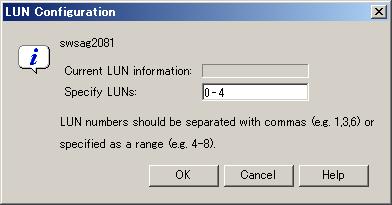
[For the Fibre Channel switch that is in no-zone status] If "Configure WWPN_Zoning on the switch when access paths are created." is selected when the Fibre Channel switch is registered with this software product, a dialog opens to ask about whether to set zoning in the Fibre Channel switch. The security function of the Fibre Channel switch is used if zoning is set in a place without zoning. Note that operation of other active access paths is disabled by this security function. In such a configuration, it is recommended to stop operation of other access paths, and set the access paths again from this software product. If "Do not configure WWPN_Zoning on the switch when access paths are created." is selected when the Fibre Channel switch is registered with it, the above dialog does not appear. To change "Do not configure WWPN_Zoning on the switch when access paths are created." to "Configure WWPN_Zoning on the switch when access paths are created.", change the setting according to the property zoning information about the Fibre Channel switch.
Check access path information when it is displayed. If the displayed information need not be modified, click [OK]. This software product sets an access path for the device.
If a storage area used in this access path setting is defined in another HBA, an area collision warning message is output. (Only the ETERNUS8000, ETERNUS6000, ETERNUS4000, ETERNUS3000, ETERNUS2000 series and the GR series provide this check mechanism on the storage side.) The access path setting is required if the storage area is defined from several HBAs in multipath disk control or on the cluster system. In other configurations, recheck the settings because data may have been corrupted.
The message showing the normal end of the access path is displayed. Check the contents, and click the [OK] button.
In Solaris OS server nodes, the status of this access path is normal (Blue). In other OS server nodes, the status of this access path is normal (Green) or normal (Blue). At this time, a momentary HBA error causes the HBA to go to "warning!" status. From [View], execute [Refresh] and then verify that the latest status is effective. When setting several access paths simultaneously, perform step 6 and after to add the access paths. When an access path is set in Windows2000 or Windows2003, devices are automatically recognized according to the number of the LUNs set in the access path, and a device addition message is displayed. Alternatively, the device addition message may be output to the event log as Removable Storage. However, a prerequisite is that the device support plug&play. (ETERNUS/GR supports this function.)
For ETERNUS storage devices, "Host response" related to [Host worldwide name] of the preset host affinity is "00" for the ETERNUS3000 or "Default" for the ETERNUS8000, ETERNUS6000, ETERNUS4000 and ETERNUS2000.
Change the "Host response" setting by ETERNUSmgr, if necessary. For details, refer to the related ETERNUS disk array manual.
[Setting an access path for a tape in Solaris OS] Write information such as a LUN number in a configuration definition file (e.g., st.conf) for the target tape driver. If the HBA is the SN10-FC01 or FC64-1063, however, WWPN binding information must also be written. After the access path has been set, the following tape driver can display LUN information: st,ftla,fsct,IBMtape,mt,lb,sg.
[GR720/GR730 (version V11L21 or earlier)/GR740, GR820, GR840 (version V03L52P1939 or earlier)] Restart the GR device. The device must be restarted to reflect the GR settings defined from this software product. However, unspecified versions and some of the GR740, GR820, GR840P19 versions (for these versions, contact Fujitsu) need not be restarted because the ETERNUS8000, ETERNUS6000, ETERNUS4000, ETERNUS3000 and ETERNUS2000 series supports the hot system configuration setting reflection function.
[Under the hddvadm-M execution environment, where the hot system expansion function of multi-path disk control (ETERNUS Multipath Driver 2.0.1 or later, GR Multipath Driver 1.0.4 or later) has been set in the Solaris OS server node] Execute the command below on the target server node to enable the server node to recognize the storage device.
When PW008FC2A, PW008FC2-G, PW008FC3, GP7B8FC1A, GP7B8FC1-G, GP7B8FC1, SE0X7F11F or SE0X7F12F is set as the access path for HBA, the driver validates the set information. Execute a command to change the hot system expansion properties of the driver. Execute the following FUJITSU PCI Fibre Channel driver command:
# /usr/sbin/FJSVpfca/fc_config -v
Note that the server must be rebooted for a FUJITSU PCI Fibre Channel driver that does not support this command. Use the following command to reboot the server node:
# /usr/sbin/shutdown -y -i6 -g0
To automatically build a multipath device, execute the grmpdautoconf command. For details on the command, see the driver manual.
# /usr/sbin/grmpdautoconf
To automatically build a multipath device that uses the ETERNUS multipath driver and has a path passing through multiple Fibre Channel switches, execute the command after confirming path redundancy and specifying the "-X" option (because the grmpdautoconf command cannot check whether the redundancy of a path passing through multiple Fibre Channel switches is guaranteed).
# /usr/sbin/grmpdautoconf -X
[On a Solaris OS server node with multipath disk control (GR multipath driver 1.0.3 or earlier, MPLB, MPHD, HDDV2.2 or later) and hot system expansion specified (hddvadm -M execution environment)] Execute the following command on the target server node so that the target server node recognizes the storage unit.
When PW008FC2A, PW008FC2-G, PW008FC3, GP7B8FC1A, GP7B8FC1-G, GP7B8FC1, SE0X7F11F or SE0X7F12F is set as the access path for HBA, the driver validates the set information. Execute a command to change the hot system expansion properties of the driver. Execute the following FUJITSU PCI Fibre Channel driver command:
# /usr/sbin/FJSVpfca/fc_config -v
Note that the server must be rebooted for a FUJITSU PCI Fibre Channel driver that does not support this command. Use the following command to reboot the server node:
# /usr/sbin/shutdown -y -i6 -g0
In Solaris 9 OS, hddv.conf is edited if needed (see the multipath disk control (GR Multipath Driver, MPLB, MPHD, HDDV) various driver manuals). The following command is executed on the server node to fetch a storage device.
# update_drv -f hddv
If the Solaris version is other than the Solaris 8 OS and Target ID which is specified at this software product access path setting is already defined (reserved) in hddv.conf file, execute the command below on the target host to fetch device information.
# /usr/sbin/hddvadmdr
If the Solaris version is other than the Solaris 8 OS and Target ID which is specified at this software product access path setting is not defined (not reserved) in hddv.conf file, write the target ID into hddv.conf and execute the command below on the target host to fetch device information.
To reserve space for future expansion, during hddv.conf editing, remove the comment characters on the lines for the Target ID and LUN involved. Then, after the next reboot, hot system expansion is enabled without another reboot. If the Fibre Channel interface is used to reserve this space, specify 16 or a higher number for the Target ID. Make sure that the Target ID number is not the same as that in sd.conf.
# touch /reconfigure
# /usr/sbin/shutdown -y -i6 -g0
With the above setting, the hddv driver can recognize the logical storage unit. If necessary, execute the command that builds an extension path to the multipath instance or the command that configures the multipath instance. For information about the commands, refer to the applicable driver manual (mplbconfig/iompadm add/iompadm new). After executing this driver command, click the multipath instance in the Server view. The extension path in addition to the existing path is highlighted. This indicates a correctly incorporated path.
[Under the hddadm-m execution environment, where the non-hot system expansion function of multi-path disk control (GR Multipath Driver, MPLB, MPHD, or HDDV) has been set in the Solaris OS server node or under the environment that does not use the multi-path disk control] Execute the following command on the target server node to enable the server node to recognize the device:
If the HBA is XSEFC401AF, XSEFC402AF, SG-XPCI1FC-QF2, SG-XPCI2FC-QF2, SG-XPCI1FC-QL2 or SG-XPCI2FC-QF2-Z
Check the storage Ap_id using the cfgadm -al command, and make the OS recognize the LUN using the cfgadm -c configure Ap_id command. For details about the commands, check the man command.
Non-GR Multipath Driver, MPLB, MPHD, or HDDV environment (including the tape environment)
# touch /reconfigure
# /usr/sbin/shutdown -y -i6 -g0
GR Multipath Driver, MPLB, MPHD, or HDDV environment
# touch /reconfigure
# /usr/sbin/shutdown -y -i6 -g0
# hddvadm -m (The required part of sd.conf is moved to hddv.conf, and the saved mphd.conf/mplb.conf file is restored.)
# touch /reconfigure
# /usr/sbin/shutdown -y -i6 -g0 (mphc.conf/mplb.conf is restored. The existing instances of various drivers (mplb/mphd/hddv) are built.)
According to the environment, execute the command that builds an extension path to the multipath instance or the command that configures the multipath instance. For information about the commands, refer to the applicable driver manual (mplbconfig/iompadm add/iompadm new). After executing this driver command, click the multipath instance in the Server view. The extension path in addition to the existing path is highlighted. This indicates a correctly incorporated path.
[Solaris OS server node] Arrange the files in /dev/rdsk with # disks -C command.
[Windows] Restart the unit so that the device is recognized. Even if the device is automatically r ecognized by Windows 2000 or Windows 2003, Fujitsu recommends restarting the unit so that the device is recognized again.
[Linux server node] Restart the unit so that the device is recognized.
[HP-UX server node] Restart the unit to execute device recognition. After restart, check the connection of the device and search for the device file (for example, /dev/dsk/c5t1d0) with #ioscan -funC disk command. If the device file does not exist, create the device file by executing #insf-H <H/W pathname > -e command for H/W path in which the device file is not detected.
[Other server nodes] Perform operations for device recognition.
Check the access path from this software product.
[For Solaris OS server node] /dev/rdisk/cXtXdX is created on the server node side. Note that executing [Refresh] from this software product displays the access path. If it is possible to check that the LUN was recognized by the OS, the access path will change to normal (Green).
(If the HBA is XSEFC401AF, XSEFC402AF, SG-XPCI1FC-QF2, SG-XPCI2FC-QF2, SG-XPCI1FC-QL2 or SG-XPCI2FC-QF2-Z, it is not possible to check whether LUN is recognized by the OS. For this reason, the access path remains as Normal (Blue) and does not change.)
[Windows server node] A device is generated on the server node side. Using the same method, you can also set access path specification by selecting the server node from storage.
[Linux server node] A device is generated on the server node side. Using the same method, you can also set an access path by selecting the server node from storage.
[HP-UX server node] A device is generated on the server node side. Using the same method, you can also set an access path by selecting the server node from storage.
You can set an access path between server nodes (HBAs) and between storage systems (CAs) by performing drag&drop operations between ports in the Server node view. In such cases, the only action necessary is to set one-to-one WWPN zoning on the Fibre Channel switch. Therefore, one requirement is that WWPN zoning of the Fibre Channel switch can be set. The GUI window cannot display access paths between server nodes(HBAs) and between storage systems (CAs) in a diagram. Check the zoning information in Fibre Channel switch properties. Also, delete an access path according to this zoning information.
To define the GR740 configuration after setting an access path, read existing GR740 configuration definition information from the device, edit it, and transfer it to the GR side. If the existing information is not used on the GR740 side, security settings defined by this software product may be overwritten.
This software product can delete access paths set by it and access paths for which one-to-one WWPN zoning is set for Fibre Channel switches. It can delete access paths only in the Fibre Channel switch environment.
Such an access path can be deleted even if the access path state is Config miss Match. Select and delete the access path whose state is Config miss Match in the window.
Delete an access path for which one-to-one WWPN zoning is set for a Fibre Channel switch between server nodes (HBAs) or between storages (CAs) according to the zoning information in Fibre Channel switch properties.
The access path cannot be deleted to change the zone status of the switch to non-zoning (No Security). All the zoning settings of the switch are deleted when a user request to delete an access path is processed, this software product creates a dummy zone. Although the loss of zone security as a result of deleting zoning can lead to inadvertent accessing of disk areas during operation, the dummy zone created prevents data destruction.
When changing the zone status of the switch to non-zoning (No Security), manually change the zone status of the switch to No Security. Note that this dummy zone will not be deleted even if access path addition processing is executed.
Only an administration account, whose authority level is "privileged administrator", can delete access paths.
You cannot delete access paths defined during setup other than for setting one-to-one WWPN zoning such as port zoning, WWNN zoning, or multi-port WWPN zoning in a Fibre Channel switch. (Only the one-to-one WWPN zoning setting is valid in this software product.) In such cases, delete a zone from the zone information of Fibre Channel switch properties, or log in directly to the Fibre Channel, and change the setup.
Select [View]-[Refresh] from the menu or press [F5], and verify that all Fibre Channel switches cascaded to the Fibre Channel switch associated with the access path setting can be correctly recognized in the current status. Once an access path is changed because a Fibre Channel switch is temporarily disconnected from the cascade connection, the old cascade connection cannot easily be recovered. (In this event, execute the cfgClear command to delete zoning information for the Fibre Channel temporarily disconnected from the cascade connection. This enables cascade reconnection.)
If multipath control for Windows is used as the Windows 2000/2003 multipath driver, be sure to shut down the server node before deleting an access path. If an access path is deleted while the server node is in operation, a very long time is required to shut down the server node later because of the operation of Windows path detection logic.
To delete the access path of Windows 2000/2003 multipath control for Windows on the same server node as the admin server from this software product, shut down the admin server, disconnect the FC cable from the access path to be deleted, restart the admin server, and delete the access path.
For Unix, execute umount for the access path to be deleted.
When ETERNUS Multipath Driver 2.0.1 or higher is used and the access path to be deleted is physically connected to a Fibre Channel switch for which no zone is set, physically remove the access path in advance such as by disconnecting the cable for which access path deletion is to be executed.
Delete a set access path. You can also delete the access path whose state is [Config miss Match] (incorrectly set access path).
[Solaris OS (GR Multipath Driver, MPLB, MPHD environment)] Release the multipath setting.
Refer to the relevant driver's manual for information on the command and command parameters.
If GR Multipath Driver or MPLB 2.2 and higher, execute the following command:
# mplbconfig (arguments are required, -d option)
If MPLB 2.1 and former or MPHD, execute the following command:
# iompadm (arguments are required , destroy option)
MPLB2.1 or earlier and MPHD do not support the commands that add and remove paths. Delete the multipath instance by using the above command (iompadm destroy).
[Solaris OS (GR Multipath Driver, MPLB, MPHD, HDDV environment)] Release HDDV.
When the hot system expansion function of server node is disabled, execute the following commands:
# hddvadm -i
hddv.conf is moved to sd.conf, and the mphd.conf/mplb.conf file is saved.
[Windows] If multipath disk control for Windows is set, shut down the Windows server node. If the Windows server node is active in this environment, this software product suppresses access path deletion.
In this software product, click the target access path, and select [Operation(C)]-[Access Path]-[Delete] from the menu. Alternatively, click the target access path to select it, right-click it, and then, select [Access Path]-[Delete] from the popup menu.
Select the displayed access path to be deleted. Then, click the [OK] button to confirm deletion and delete it. (When an access path used for Windows 2000 or Windows 2003 is deleted, a warning message appears as many times as the number of LUNs set for the access path.)
[Solaris OS (Agent available)] After the access path has been deleted, its state may remain Config miss Match (yellow) until the server node is restarted. (If WWPN binding is set on the server node)
[ETERNUS Multipath Driver 2.0.1 or higher] Execute the grmpdautoconf command to implement path removal.
(For details of the command specifications, see the ETERNUS Multipath Driver User's Guide.)
# /usr/sbin/grmpdautoconf -d
If the HBA is the PW008FC2A, PW008FC2-G, PW008FC3, GP7B8FC1A, GP7B8FC1-G, GP7B8FC1, SE0X7F11F, SE0X7F12F, the port property described in /kernel/drv/fjpfca.conf may be deleted by executing the grmpdautoconf command. After executing the grmpdautoconf command, reset the property as needed. For details on the setting contents, see "4.1.1 Solaris OS server node (host)".
[GR720/GR730 (version V11L21 or earlier)/GR740, GR820, GR840 (version V03L52P1939 or earlier)] Restart the GR device. The device must be restarted to reflect the GR settings defined from this software product. However, unspecified versions and some of the GR740, GR820, GR840P19 versions (for these versions, contact Fujitsu) need not be restarted because the GR side supports the hot system configuration setting reflection function.
[Solaris OS] Follow the procedure below so that the server node recognizes the storage unit.
In the hot system expansion (hddvadm -M) environment of ETERNUS Multipath Driver 2.0.1 or higher, GR multipath driver, MPLB, MPHD, or HDDV, execute the command shown below. After path removal, the server must be restarted to enable the Fibre Channel card definition of the server node.
# /usr/sbin/shutdown -y -i6 -g0 (restarts the server)
# disks -C (execute with Solaris 7 OS or higher)
In an environment using the GR multipath driver, MPLB2.2 or later, MPHD, and HDDV with non-hot system expansion or normal specified (hddvadm -m), execute the following operations:
If the deleted target ID is not used in the sd.conf file, edit sd.conf to delete the target ID. (Do not delete it if it is used by another device.)
#touch /reconfigure
# /usr/sbin/shutdown -y -i5 -g0
Start it in single user mode.
# hddvadm -m (The required part of sd.conf is moved to hddv.conf, and the saved mphd.conf/mplb.conf file is restored.)
#touch /reconfigure
#/usr/sbin/shutdown -y -i6 -g0 (Instances for each driver (mplb/mphd/hddv) are configured when the definition file is restored.)
# disks -C (execute with Solaris 7 OS or higher)
In an environment using MPLB2.1 or earlier
If the deleted target ID is not used in the sd.conf file, edit sd.conf to delete the target ID. (Do not delete it if it is used by another device.)
#touch /reconfigure
# /usr/sbin/shutdown -y -i5 -g0
Start it in single user mode.
# hddvadm -m (The required part of sd.conf is moved to hddv.conf, and the saved mphd.conf/mplb.conf file is restored.)
#touch /reconfigure
# /usr/sbin/shutdown -y -i6 -g0
# disks -C (execute with Solaris 7 OS or higher)
Reconfigure the multipath by using the new #iompadm command.
In an environment where neither the hard disk driver (HDDV) nor multipath control (GR multipath driver, MPHD MPLB) is used
#touch /reconfigure
# /usr/sbin/shutdown -y -i6 -g0
# disks -C (execute with Solaris 7 OS or higher)
Check the access path from this software product.
[Windows] Restart the device.
[Linux] Restart the device.
[HP-UX] Restart the device.
[Other server nodes] Perform operations for device deletion recognition.
Storage affinity (WWPN binding) is deleted but LUN settings of the related /kernel/drv/sd.conf file are not deleted in consideration of security. If a definition must be deleted, edit the /kernel/drv/sd.conf file directly on the server node side.
This software product sets WWPN-based security settings on a device to form an access path. However, when the faulty part such as an adapter (controller) is replaced, the WWPN name may be changed because it is unique.
Devices whose WWPNs are changed when the faulty part such as an adapter (controller) is replaced: All HBAs and bridges such as the LT120, LT130, LT160 and LT230.
Devices whose WWPNs are not changed when the faulty part such as an adapter (controller) is replaced: The ETERNUS series, GR series, LT250, LT270, and Symmetrix, etc.
Operation can be performed as is if WWPNs are not changed. If WWPNs are changed because an adapter (controller) is replaced, security functions of the WWPNs constituting the access path must be changed to those of new WWPNs. This operation is defined as "access path inheritance" and it provides a function that automatically reconfigures the WWPN security settings managed by this software product.
For Replacement of the parts of supported device and access path inheritance, refer to "8.3 Replacement of the Parts of Supported Device".
This software product uses one-to-one WWPN zoning in general access path setting. Also, it provides a function that checks for the type of zoning is set on the Fibre Channel switch. If an unused zoning setting remains after a device is deleted because of an undeleted access path, this window can be used to delete the unused zoning setting.
"Zoning Information" displayed in Fibre Channel Switch property serves this function.
The zone name set in the Fibre Channel switch and the WWPN defined in the zone name are displayed as these properties.
If one-to-one zoning is set, two WWPNs exist under one zone name. If zoning is set based on several WWPNs and port information, WWPN information where simultaneous both-way access is possible is displayed under the zone name.
You can delete a zone displayed next to the Delete check box directly by checking the check box and clicking the [Delete the checked zoning information] button.
One-to-one WWPN zoning setting is recommended in this software product to realize the complete zoning security management as described in "4.2.1 SN200 (Brocade) Fibre Channel switch", though port zoning is possible to be performed. The procedure to change into one-to-one WWPN zoning setting is as follows.
Confirm that all the monitored devices are connected with all the switch ports.
It is necessary that the definition file (sanma.conf) must be changed. Refer to "D.2 sanma.conf Parameter" and specify 1 in SET_SW_ZONING_ALWAYS.
By selecting the [Re-read Definition File] button in [Option] in [Tool] in menu or restarting the administrative Manager operates to cause the change to be reflected the contents of this file.
Display "Zoning Information" shown in Fibre Channel Switch property.
Open host server or storage side view based on port zoning information.
If a host node name or a storage name in "Zoning Information" displayed in Fibre Channel switch property is not shown, register the device connected with Fibre Switch Port by using manual embedding function.
Select access path and execute [Access Path] - [Connect].
Display "Zoning Information" of Fibre Channel switch again after normally finishing the access path setting.
Confirm that the same contents of WWPN zoning as those of port zoning is displayed and delete the specified port zoning.

If the multiple port zoning setting is executed, remember not to delete the multiple port zoning until WWPN zoning relevant to each other is set.
Repeat the procedure from steps 3 to 7.
If necessary, return the setting that is executed in step 2 to the former setting.
To change the zoning setting can be executed in zone administration window in WEBTOOLS in Fibre Channel switch and by Telnet function.
This product software receives and decodes an SNMP Trap that is sent from a device, and handles a device status change as an event for managing device errors.
The event is created based on the contents of SNMP traps and user settings.
The processing described below is performed for generated events.
Displaying event logs
Displaying device events
Systemwalker Centric Manager linkage
Shell/Bat linkage
External script linkage
As for the following event, this software product only displays event logs and device events (as for some events only event logs are displayed), and other processing are not performed.
Events by user operations (all the events in "Chapter 1 Events Related to Operation of This Product " in " ETERNUS SF Storage Cruiser Event Guide")
Trap events common to devices (the trap common to devices in "Chapter 2 Events in Notifications Sent from Monitored Devices " in " ETERNUS SF Storage Cruiser Event Guide")
Start of performance data re-collection/Success of performance data re-collection event (Success of performance data re-collection, Success of performance data re-collection in "2.8 Explanation of Performance Management Traps" in "ETERNUS SF Storage Cruiser Event Guide")
Event that indicates when the state changes into error(red) in the device polling function ("When the state changes into error(red)"in the device polling function "Chapter 3 Device Polling Event" in " ETERNUS SF Storage Cruiser Event Guide")
For detailed information on how to customize SNMP Trap processing, see "Appendix D Customization".
Displaying event logs
Generated events are displayed in the event log of Client. To display the event log, select [View]-[Show/Hide]-[Event Log] from the menu, and select Show/Hide. Events are displayed shown as below.
|
Displayed items and descriptions |
details |
|---|---|
|
Status |
Displays the level of a displayed event. |
|
Date |
Displays time and date event occurred in Month DD, YYYY HH:MM:SS AM (or PM). |
|
Device Name |
Displays the name of a device on which the event occurred. |
|
Monitor |
Indicates the name of the admin server that detected the monitor event. |
|
Event ID |
Displays this ID when the event has the corresponding ID. This ID is defined in the administrative Manager that is monitoring the event. |
|
Event Information |
Indicates event details. Refer to ETERNUS SF Storage Cruiser Event Guide for the detail information. |
A displayed example of an event log is shown below. One line of an event log can be copied in the clipboard. By this function, event log information can be attached to E-mail text to be sent.
The procedure is as follows:
Select the event log to copy, and display the popup menu and execute [Copy EventLog to ClipBoard]. This execution enables the event log information to be copied in the client clipboard.
Displaying device events
Generated events are displayed as device events of Client. Users can check for device events from "Property" for a device.
Systemwalker Centric Manager linkage
Also, generated events are reported to Systemwalker Centric Manager. For information on settings required in advance, see "10.2 Linkage with Systemwalker Centric Manager". The importance levels of the events are also reported.
Events of the server node agent is not reported to Systemwalker Centric Manager. (Shell/Bat linkage is operated.) Execute fault monitoring by message monitoring function of Systemwalker Centric Manager.
Shell/Bat linkage
A generated event is specified in the call argument of the Shell file, such shown as below.
[Manager for Solaris OS] /etc/opt/FJSVssmgr/current/trapop.sh argument-1 argument-2 argument-3 argument-4 argument-5 argument-6
[Manager for Linux] /etc/opt/FJSVssmgr/current/trapop.sh argument-1 argument-2 argument-3 argument-4 argument-5 argument-6
[Manager for Windows] administrative_server_environment_settint_directory\Manager\etc\opt\FJSVssmgr\current\trapop.bat argument-1 argument-2 argument-3 argument-4 argument-5 argument-6
argument-1 is the fault detail for the target device.
argument-2 is the IP address for the target device.
argument-3 is the server node name (FQDN) for the target device (if the full domain name cannot be confirmed, the IP address is set).
argument-4 is the number of milliseconds that have elapsed from 00:00:00 GMT 01 Jan 1970 ("zero") to the current time.
argument-5 is the fault level ("INFO", "WARNING"," ERROR").
argument-6 is the icon name for the target device.
Rewriting the content of these shell/bat files enables the e-mail linkage of fault information or other Management Software linkage (such as issuing commands to Management Software and writing information to a log file managed by Management Software).
Sample Shell/Bat files are installed in the directories shown below.
Copy this sample and create Shell/Bat files for linkage.
[Manager for Solaris OS] /opt/FJSVssmgr/lib/sample/trapop.sh
[Manager for Linux] /opt/FJSVssmgr/lib/sample/trapop.sh
[Manager for Windows] administrative_server_environment_settint_directory\Manager\opt\FJSVssmgr\lib\sample\trapop.bat
If the Shell/Bat linkage function is not used, there is no need to create these Shell/Bat files.
External script linkage
Any external script other than trapop.sh/trapop.bat of Shell/Bat linkage can be executed. Up to two scripts can be defined in each SNMP Trap XML definition file. Arguments for calling such scripts are common to those for Shell/Bat linkage.
For information about the methods for defining, see "D.6 SNMP Trap XML Definition File".
External script linkages must be defined in the SNMP Trap XML definition file. Therefore, they are not available on devices where XML definition files are not provided.
For shell scripts or batch files in Shell/Bat linkages or external script linkages, do not output processing results and processing progress on the screen (for example, do not perform such a process as displaying a message with the echo command). Be sure to describe "@echo off"at the head under Windows.
Users can customize the displaying of events and descriptions of linkage for individual SNMP Traps. For details, see "D.6 SNMP Trap XML Definition File".
The following is an example of each Shell/Bat file.
[trapop.sh sample for Solaris OS and Linux] The events of this software product are reported by mail. (This requires the SMTP server and Manager to be running on the admin server. The path of the mail command may differ from the sample. Change it so that it is appropriate for the operating environment.)
|
#!/bin/sh #HOSTNAME=`/bin/hostname` #MAILCMD=/bin/mail#TMP_FILE=tmp_mail_file.$4 # #echo "To: $MAILADDRESS" > $TMP_FILE #echo "Subject: SAN manager($HOSTNAME) event mail" >> $TMP_FILE #echo "" >> $TMP_FILE #echo "-----------------------------------" >> $TMP_FILE #echo " Storage System manager event mail " >> $TMP_FILE #echo "-----------------------------------" >> $TMP_FILE #echo $1 >> $TMP_FILE # #$MAILCMD $MAILADDRESS < $TMP_FILE #/bin/rm -f $TMP_FILE |
After defining the setting in trapop.sh as described above, executing grtraptest command which is described in "3. Check Systemwalker Centric Manager linkage and Shell/Bat linkage of events" in "5.3 Checking Management Status" transfers mail to a destination. Therefore, whether it is possible to link with Shell/Bat can be confirmed by generating SNMP Trap.
[Sample of trapop.bat for Windows] The event of this product is notified by mail. (To actually operate, an UNIX system server with sendmail that supports the SMTP protocol or a Windows Server that support standard SMTP service is necessary.)
|
@echo off rem ## CAUTIONS ## Please do not comment out or delete the line of "@echo off" |
|
|
rem set INSTALL_DIR=install-dir rem set MAIL_SERVER_ADDRESS=mail@server.address rem set MAIL_FROM=StorageManager rem set MAIL_TO=your@e-mail.address |
->Write the install DIR ->Write the address of mail server ->Write the mail address of the sender ->Write the mail address of the receiver |
|
rem cd %INSTALL_DIR%\etc\opt\FJSVssmgr\current rem set STXSMAIL=stxsmail.exe rem set TMP_FILE=tmp_mail_file.%4 rem echo From: %MAIL_FROM% > %TMP_FILE% rem echo To: %MAIL_TO% >> %TMP_FILE% rem echo Subject: Storage system manager(%COMPUTERNAME%) event mail >> %TMP_FILE% rem echo.>> %TMP_FILE% rem echo ----------------------------------- >> %TMP_FILE% rem echo Storage system manager event mail >> %TMP_FILE% rem echo ----------------------------------- >> %TMP_FILE% rem echo %1 >> %TMP_FILE% rem set MAILCMD=%STXSMAIL% %MAIL_SERVER_ADDRESS% %TMP_FILE% rem %MAILCMD% rem del %TMP_FILE% |
|
Event information can be sent by starting the stxsmail program with the mail client function in the Bat file.
To edit this Bat file properly, please refer to "Appendix F A Mail client function program with the Windows Version of Manager (stxsmail)" for details.
Execute "3. Check Systemwalker Centric Manager linkage and Shell/bat linkage of events". of "5.3 Checking Management Status" with the above setting, the mail as below is forwarded to the destination mail address. By this way, the Bat linkage can be confirmed.
To perform Systemwalker Centric Manager linkage, Shell linkage, or external script linkage, either register the IP address and host name information for each device in the DNS server that is referenced by the administrative server, or define them in the /etc/hosts file on the administrative server so that the names of the devices registered in this product can be resolved.
The flasher icon is displayed on the upper right corner of the resource management or Side view to inform that information on a device registered with this software product was updated.
The dialog is displayed when lighting revolving light icon is clicked, the device status is updated to latest information when [OK] is selected, and the latest state of the device is displayed on the screen.
Moreover, the trouble level can be distinguished by the color of revolving light.
Displaying revolving light icon
Display revolving light icon on the status bar(under of the window) on the upper right corner of the resource management view or Side view.
Color of revolving light icon
Revolving light icon is displayed the state change of the device in red, yellow and green and notifies the event level. When the state of the device is changeless, it displays it in the gray.
For information about details and color of revolving light icon, see "Table 6.2 Revolving light icon state", in "6.1.1 Main view".
Updating to latest information
The dialog is displayed when revolving light icon is clicked, the device status is updated to latest information when [OK] is selected, and the latest state of the device is displayed on the screen.

When [Cancel] is selected, the update process to latest information is not done. Update to latest information by either of the following methods:
Click revolving light icon again and display dialog and select [OK].
Select [View]-[Refresh].
Press the [F5] key.
When the [Help] button is selected, the pertinent message of Message Guide is shown.
Priority of Revolving light icon lighting
Revolving light icon lights in order with high event level.
|
Event level |
low ------------------------> high |
|
Color |
gray -> green -> yellow -> red |
Example:
Revolving light icon lights in red when the event at the trouble level is generated when Revolving light icon lights in yellow.
Revolving light icon lights in red when the event at the information level is generated when Revolving light icon lights in red.
|
Contents
Index
|