

| ETERNUS SF Storage Cruiser User's Guide 13.2 - Solaris (TM) Operating System / Linux / Microsoft(R) Windows(R) - |
|
Contents
Index
|
This chapter explains device definitions and operation flowcharts required for operating this software product.
Transitions of the Client window are as follows:
Select [Programs] - [ETERNUS SF Storage Cruiser] - [Storage Cruiser] from the Start menu of an administrative client or double-click the Storage Cruiser icon positioned on the desktop.
The login window shown below is displayed. Enter the administrative server address (IP address/node name) where Manager is operating, and the user name/password, and then click the <OK> button. If at this point, you want to change the communication port number to the administrative server, click the [Port] button and change the port number.

Note that the user registration, password, and access authority can be changed. Refer to "5.4 Setting Up a Login Account".
Administrative server information (IP address/node name) is managed from a personal computer on which Client is installed. To not use any item of administrative server information, select the name of the applicable server, and select [Delete].
If at this point, you want to change the communication port number to the administrative server, click the [Port] button and change the port number.
The client window is displayed.

If the changes you made in the IP address of the administrative server are not reflected in the manager, the main view may not be displayed. In such a case, see administrative server information change commands in "Appendix C Command References" to check for a problem in the IP address setting of the administrative server.
When monitored server nodes have duplicated server node names or monitored storage devices have the same SysName, device names assigned for finding, adding, or manual embedding of the corresponding devices may already exist in the management database.
In this case, the device name may be registered with trailing ".suffix-number".
A suffix number is assigned in ascending order from 0.
Example: ServerNode.0, ServerNode.1, and ServerNode.2 ...
For device management using this software product, it is necessary to first conduct a device search and then display the devices to be managed on an GUI window. There are two methods for conducting a device search, both of which are described below. Icons indicating detected devices are placed in the undefined state, and these device icons are displayed in violet. Once a device is detected, its icon is recorded as undefined in the database. To delete this icon, delete the corresponding device.
When detecting devices, the SMIS device (virtualization switch VS900, etc.) adds the device.
When detecting devices, the ESC and SSC agent automatically adds the device.
For the device in SAN catagory which is classified as SAN device, it may not displayed in domain view after executing device search. To display the device, choose the device type from tree or SAN category.
Detecting for devices in the same subnet as the administrative server automatically
On the tree, select main view item or the base domain in the storage category and then select [File]-[Detect SAN devices]-[Detect device in subnet]. Either of these operations displays the icons of those devices that are supported by Manager and that are subject to the automatic detection function. SNMP-based broadcast processing is performed internally, and the icons of the devices supported by this software product are automatically displayed. The automatic device detection function can be used for other subnets as well, by the changing of the definition file. (For details, see "Appendix D Customization".) However, note that this function is supported only in those environments where broadcast transmission passes through other subnets.
When [View]-[Change] and [List View] is selected, device search from the physical resource view cannot be performed.
If [Detect device in subnet] does not work, make a check as follows:
For devices that do not support [Detect device in subnet] as described in "1.3.5 Support levels," use the method described below for detecting a device with the specified IP address.
For each device, check the SNMP communication settings. If the SNMP Community name on the device side has been changed, also change the settings of this product accordingly (see "Appendix D Customization".)
Detecting a device by specifying an IP address
To detect ESC or SSC Agent, select main view item or the base domain in the server category on the tree, and then select [File]-[Register]-[Register server]. Alternatively, right-click anywhere in the map view, and select [Register]-[Register server] from the pop-up menu displayed. When the device search window is displayed as shown below, enter an IP address, such as "10.10.10.10", and click the <OK> button.
To detect any device other than ESC or SSC Agent, select main view item or the base domain in the storage category on the tree, and then select [File]-[Detect SAN devices]-[Detect by IP address(F)]. Alternatively, right-click anywhere in the map view, and select [Detect SAN devices]-[Detect by IP address] from the pop-up menu displayed. When the device search window is displayed as shown below, enter an IP address, such as "10.10.10.10", and click the <OK> button.
Automatic detection
This function is used to search for devices except SMIS device. Enter an IP address (such as "10.10.10.10") and click the <OK> button.
Detection by type specification
This function is used to search for SMIS device.
Detection of a SMIS Switch device (Searching for virtualization switch device VS900)
From the pull-down menu, select "SMIS Switches," enter the following information, and then click the <OK> button.
- IP address information
Enter the IP address (such as "10.10.10.10") of the administrative server on which SMI Agent is installed to manage the virtualization switch device VS900.
When the cluster system uses SMI Agent, specify the cluster-inherited IP address.
- NameSpace
This is name space information used to access SMI Agent.
Enter "root/brocade1".
- Login account
Enter an account name with which you can log in to the administrative server on which SMI Agent is installed. This is not an account name used to log in to a switch device.
- Login password
Enter a password with which you can log in to the administrative server on which SMI Agent is installed. This is not a password used to log in to a switch device.
- Port Number
Enter the port number of SMI Agent.
The default port number is 5988.
If another application is using 5988 on the administrative server on which SMI Agent is installed, change the port number of SMI Agent by referring to the "SMI Agent User's Guide," and then specify a new port number.
Devices that are successfully detected are automatically added. If this automatic addition fails, said devices must be added manually.
For details of how to add devices, see "5.2.2 Adding a device (changing from the violet icon state to the registered state)".
When asked for a user name and a password, enter the Login account and Login password indicated above.
If such a search for a product in the ETERNUS8000 series, the ETERNUS6000 series, the ETERNUS4000 series, the ETERNUS3000 series , the ETERNUS2000 series or GR series fails, check the following items:
The SNMP environment has not been set up from ETERNUSmgr/GRmgr since installation of the device
Action: The SNMP agent of the device is not active. Set up the SNMP environment as instructed in "4.3.1 Disk array ETERNUS8000, ETERNUS6000, ETERNUS4000, ETERNUS3000, ETERNUS2000, ETERNUS VD800, GR".
In the case of GR740,820,840
Action: Check whether the GRG (GR Gateway) is running on the maintenance PC. If not, register GRG.exe from the Windows start menu, and activate it.
If such a search for ESC or SSC Agent fails, check the following items:
ESC or SSC Agent is not activated.
Action: Activate ESC or SSC Agent.
The storage affinity is set to the WWNN (World Wide NodeName), PID, or TID binding
Action: Set the storage affinity to the WWPN (World Wide PortName) binding.
To enable management of undefined devices whose icons are displayed in violet, the devices must be registered with this software product.
Select the icon of a device to be registered and then select [File]-[Register]-[Register SAN devices]. Alternatively, right-click the device icon and select [Register]-[Register SAN devices] in the pop-up menu.
Note: When [View]-[Change] and [List View] is selected, device addition cannot be performed from the resource view.
When the Device Addition Confirmation dialog described below is displayed, enter necessary data in each field.
User name and password
To manage the device, this software product must recognize the user name and password associated with the device.
Since each device requires different information, the items displayed in the dialog change accordingly.
<Required information>
For SN200 (Brocade) fibre channel switch and the PRIMERGY BX600 fibre channel switch blade, a user name and password with administrator rights will be required.
For SN200MDS(Cisco MDS) Fibre Channel switch, there is no required information.
For Crossroads, specify the account name and password registered by the user.
For the ETERNUS3000 M50,GR710,720, specify the password of the root account.
For the ETERNUS3000 (excluding the M50) and GRs other than the above, no user name and password are required.
Check box for enabling the SNMP Trap transmission place address automatic setting function
When a device is added, this software product automatically sets the SNMP Trap transmission place address for the device so that it can monitor for faults by using the SNMP Trap. For information about the device types for which the address automatic setting function can be used, see "1.3.5 Support levels". This setting is usually automatically made. However, when fault monitoring using this software product is not necessary, this function can be disabled by unchecking the check box in the dialog.
If the function is disabled and if the SNMP Trap setting is made manually, the "Event Notification function setup" field on the displayed list will become "Un-setting up". If the administrative server has multiple IP addresses, verifying that the correct IP address is set as the SNMP Trap transmission place for each managed device is recommended after using this function.
For information about fault monitoring required for an added device after the function is disabled, see "5.2.4 Function for setting event notification destinations". For a detailed explanation of the automatic setup, see "5.2.5 SNMP Trap transmission place automatic setting function".
The check box of "Enable fault monitorinig via SNMP traps on this device" is invalid for the device which does not support the function of automatically setting SNMP Trap transmission place.
Selecting the <OK> button registers the device.
When a Fibre Channel switch is embedded for which no zoning setting is defined (no security state), the window shown below is displayed. Check [Do not configure WWPN_Zoning on the switch when access paths are created] to start the operation without security. In such a case, when an access path is set from this software product, no zoning is set for the Fibre Channel switch. Check [Configure WWPN_Zoning on the switch when access paths are created] to set WWPN zoning when an access path is set from this software product. Considering the security of the Fibre Channel switch, the recommended selection is [Configure WWPN_Zoning on the switch when access paths are created] (bottom selection box). Clicking [Initialize] resets [Do not configure WWPN_Zoning on the switch when access paths are created.] and [Configure WWPN_Zoning on the switch when access paths are created.] to their initial settings.
If a device to be managed cannot be accessed, or if it is in any of the states described below, it cannot be registered.
Fibre Channel switch
Telnet was used to login to the target device.
Action: Log out, and then perform the registration process.
ETERNUS8000 series, ETERNUS6000 series, ETERNUS4000 series, ETERNUS3000 series, ETERNUS2000 series, GR series
User is logged into ETERNUSmgr/GRmgr of the target device.
Action: Log out, and then perform the registration process.
During the device registration process, if telnet is used to login to the Fibre Channel switch connected to the device to be registered, the physical line between the Fibre Channel switch and the device cannot be displayed because information cannot be obtained from the Fibre Channel switch. In this event, log out and execute "Refresh".
This function cancels the registration of a device being managed by this software product, thereby deleting that device from the range of management. It is used in such cases as when a device has been removed.
Click the icon of the target device, and from [File] on the menu, select [Delete]. Alternatively, right-click the device icon to display a popup menu, and then select [Delete].
Note: When [View]-[Change] and [List View] is selected, device deletion cannot be performed from the resource view.
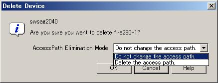
Clicking the <OK> button deletes the selected device.
If a dialog such as the one shown below opens, access path settings associated with the target device can be deleted. For example, when a server node is removed, the switch zoning setting and affinity setting for the device become unnecessary. This software product can automatically delete such unnecessary security settings. By default, this software product does not delete these settings. When "Delete the access path" is selected as the access path elimination mode from the menu of this dialog, all of the settings associated with the deleted device registered with this software product are deleted. If the access path settings must remain, such as if you want to continue to use the device while placing it outside the range of management, select "Do not change the access path".
The deleted device is displayed when it is detected again by the automatic device detection function of this software product.
Click the Virtualization Switch icon, select [File] on the menu, and then click [Delete]. Otherwise, right-click the device icon and select [Delete] from the pop-up menu.
When the virtualization switch device contains no virtual storage configuration information, perform ordinary deletion.
When the virtualization switch device contains virtual storage configuration information, the following message dialog box appears on the Client window.
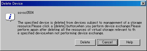
This message dialog box appears when the device contains configuration information of the virtualization switch and virtual storage devices.
To delete a virtualization switch device without replacing it:
Click the [Cancel] button in the message dialog box to stop device deletion.
From the menu on the Client window, select [File] - [Virtual Storage Window] - [View and Create], start up the Virtualization Switch Display And Create window, and then delete all virtual storage configuration information of the switch device.
Repeat deletion of the virtualization switch.
To replace a virtualization switch device:
Click the [Delete] button in the message dialog box.
Save the virtual storage configuration information and delete the target virtualization switch device.
For details, refer to the virtualization switch manual.
If fault monitoring is required for a device after the SNMP Trap transmission place address automatic setting function is disabled for the device during the device addition process, follow the procedure given below.
Select a device from the Main view, Domain view or SAN view of this software product. Then, right-click the device in the map view of the main view, domain view or SAN view and select [Event Notification function setup] from the pop-up menu.
The list display function is useful for checking whether an event notification and transmission destination is set. Check the "Event Notification function setup" field in the list. For a device with "Un-setting up" indicated, an event notification and transmission destination is not yet set.
Note that in automatic SNMP Trap setup, the device is placed in the "Un-setting up" state. The field becomes blank for a manually embedded or unregistered device.
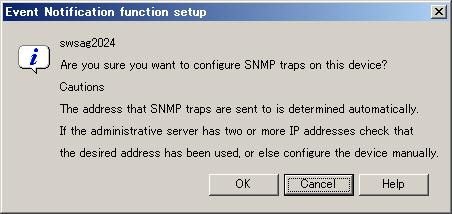
A dialog such as the one shown below is displayed. When the <OK> button is clicked, this software product automatically sets an SNMP Trap transmission place address for the device to enable fault monitoring using the SNMP Trap. For a detailed explanation of automatic setup, see "5.2.5 SNMP Trap transmission place automatic setting function".
The SNMP Trap transmission place automatic setting function, which is executed at the time of a device search or device addition, and its accuracy are explained with the figures below.
Administrative server with only one IP address
This software product automatically identifies IP address A of the administrative server and sets IP address A as the SNMP Trap transmission place for each managed device.
Administrative server with two or more IP addresses
Such an administrative server has a cluster or redundant LAN configuration or is connected to multiple subnets, and it has two or more IP addresses.
From the multiple IP addresses of the management server, this software product selects the one that is most suitable as the transmission IP address for each device. However, this logic does not work in all cases. In the environment shown in the figure below, for example, this software product may set IP address D as the SNMP Trap transmission place for managed device 1. This is because addresses cannot be automatically detected in some cases due to the nature of current LAN technology. In such an environment, therefore, it is necessary to check the SNMP Trap transmission place setting of each device after the device addition process and, if required, set SNMP Trap transmission places directly on the device side. (In the figure below, specify IP address A as the SNMP Trap transmission place for managed device 1, and logical IP address F as the SNMP Trap transmission place for managed server node 2. For information about how to set SNMP Trap transmission place addresses of server nodes manually, see "2.1 Receiving SNMP Traps".)

In order for the server node to send the SNMP Trap, agent must be installed on the host.
Some devices (such as managed servers without an agent, tape units, and NAS devices) cannot be retrieved by device search. Register these devices with this software product by using the manual embedding function.
Open the Main view or SAN view window, select [File] from the menu and then select [Manual Configuration window], or select [Manual Configuration window] from the popup menu to display the Manual Configuration window.
Select [Create New Device] from [Operation(C)] on the menu bar or use the popup menu in the Manual Configuration window.
Select the device type from the submenu (listing the types of devices that can be selected for addition). Server node, Storage, Library, Bridge, Router, or Hub can be selected for the device type. Select Storage for the NR1000.
A dialog box for entering the product type appears. Select the product type. If no product types listed are applicable, select "Other". The following is an example of selecting Storage for the device type.
A dialog box for entering device information appears. Be sure to enter the storage type because it is used as an important key during internal processing. An icon that is displayed for this product on the window can be selected using "Display Icon Setup".
"Embedding Information (Required)"
For "Device Name, "specify a unique name that can be used to manage the device. This software product uses the name as a key for identifying the device. For this reason, the name must be different from the names of other devices and server nodes within SAN management. For ETERNUS SX300, ETERNUSSX300S units, be sure to set the device name marked SANtricity.
When Storage has been selected for the device type, select the storage type from the drop-down list for "Storage Type" from among Disk, Tape, Array, Robot, and Other. Select "Other" for the NR1000.
When Bridge for a device other than a tape encryption device has been selected for the device type, specify the number of SCSI busses connected to the bridge for "Number of SCSI bus" and select [SCSI Bus Setup]. Dialog box swsag2504 appears. Enter the initiator number on the bridge side of the SCSI bus, and select [OK]. Dialog box swsag2506 appears. Specify information on the devices to be connected to the SCSI bus in the SCSI ID/LUN part, and select [OK]. If 2 or a larger number is specified for the number of SCSI busses, the procedure from swsag2504 is repeated for the number of busses.
When Router has been selected for the device type, "Number of FC Ports" and "Number of WAN Ports" are automatically set if template is selected for the product type. If "Other" is selected, enter data according to the router device configuration.
When Library has been selected for the device type, "Number of Bridge" and "Number of Drive" are automatically set if template is selected for the product type. If "Other" is selected, enter data according to the library device configuration.
"Option"
For "Manufacture Name," "Product Name," "Serial Number" (for Storage type only), "OS Type," and "OS Version" (for Server Node type only), specify appropriate information on the device. This information is displayed as property information for this software product.
For "IP Address," specify the IP address of the device when the device is connected to a LAN. If the IP address is specified here when the device supports the SNMP Trap transmission function, this software product receives SNMP Traps from the device and displays them in the event log and device event information (in the device properties). The device is also subjected to the device polling function and automatically monitored with ping (or SNMP depending on the device).
For the LT120/LT130/LT230, NR1000, and Edge, be sure to specify the IP address of the device here. However, do not specify the IP address if the device is not connected to a LAN. If the IP address is specified here for a device not connected to a LAN, the device is put in the communication disable state by the polling monitoring function and cannot be restored until it is connected to a LAN. For ETERNUS SX300, ETERNUS SX300S, enter the IP address of the SANtricity installation server in "IP address".
For "Management Software" specify how to execute software used to manage the device. Doing so enables the specified software to be called directly from the properties displayed for the device icon on the GUI window. If the Management Software can be started from the Web client, specify the corresponding URL beginning with http:// or https://. If the Management Software is an application that runs on the client, specify the full path to the executable file (c:\test\test.exe, for example).
"Display Icon Setup"
Select an icon to be used for the device.
The embedded device is displayed as a light-color icon.
Exit from the Manual Configuration window.
Select [Exit] from [File] or select the [OK] button on the lower part of the screen.
After the Manual Configuration window is changed, a dialog box appears asking "Do you want to update the administrative server with the latest information?" Select the [OK] button to update information.
Check whether the setup is correct. Use the following steps to check the setup:
Check whether every device (excluding the server node agent) can correctly receive SNMP Traps
This software product receives generic traps 0 to 5, which are SNMP Traps not unique to a specific vendor, and it decodes their contents and displays information about each event (that does not use Systemwalker Centric Manager linkage or Shell/bat linkage.) As one of generic traps 0 to 5, a COLD START trap is issued by an ordinary device. When using this trap to test whether the software product can correctly receive an SNMP trap.
A device sends the COLD START trap and other traps by turning OFF and ON the device to be managed, performing a variety of setup tasks (setup of the SNMP environment for ETERNUS/GR), doing other such work. Check whether the event is displayed with regard to the above operation and trap.
However, generic traps 0 to 5 are not normally required, so after the test is completed, you can disable display of generic traps 0 to 5 by using the following method:
Edit the following definition file:
[Manager for Solaris OS] /etc/opt/FJSVssmgr/sanma.conf
[Manager for Linux] /etc/opt/FJSVssmgr/current/sanma.conf
[Manager for Windows] administrative-server-environment-setup-directoryManager\etc\opt\FJSVssmgr\current\sanma.conf
Edit one description as follows (0=Hide, 1=Show): DISPLAY_SNMP_STANDARD_EVENT = 0;.
Select [Tool]-[Option] from the physical resource view, and then click the [Re-read Definition File] button to incorporate the definition file into a program.
Check whether server node (agent) can correctly receive SNMP Traps
[Solaris OS Agent] /opt/FJSVssage/bin/traptest <IP Address>
[Windows Agent] Agent program director\Agent\bin\traptest <IP Address>
[Linux Agent] /opt/FJSVssage/bin/traptest <IP Address>
[HP-UX Agent] /opt/FJSVssage/bin/traptest <IP Address>
In case that server node has more than 1 IP address, please input the IP address which is communicate with the admin server.
Please make sure the IP address input is correct, if the event can not be received correctly.
If the IP address is set correctly, the following event will be output when the command is executed.
SNMP Trap test command cannot linkage to Shell/bat. Please modify the SNMP definition if necessary.
To modify SNMP Trap definition, please modify ESC agent SNMP trap definition file which is located 1_3_6_1_4_1_211_4_1_3_21_2_2.xml. SNMP trap test is defined as the first number of "Specific Trap Type". You may change the action for this trap. For SNMP Trap definition file, please refer to "D.6 SNMP Trap XML Definition File".
Check Systemwalker Centric Manager linkage and Shell/bat linkage of events.
Events cannot be linked with Systemwalker Centric Manager or Shell/bat for the standard SNMP Trap. Accordingly, make an SNMP Trap occur on purpose to run the test. To test the Shell/bat linkage of an SNMP Trap of the server node agent, use the method described in step 2. To test the Systemwalker Centric Manager linkage and Shell/bat linkage of an SNMP Trap from a device, execute a tentative SNMP Trap command for the test. This command changes internal information of an SNMP Trap so that the SNMP Trap seems to have been sent from a device being monitored, and it sends such an SNMP Trap to the system's own port for receiving the SNMP Trap. Since descriptions of events are linked to Systemwalker Centric Manager and Shell/bat, Systemwalker Centric Manager linkage and Shell/bat linkage can be tested.
For the IP address of an argument, specify the IP address of a device (ETERNUS/GR or Fibre Channel switch) registered with this software product. The contents of this simulated SNMP Trap are loaded into the event log and reflected in device events (in device properties). To display the event log, click [Refresh(R)] on the menu displayed by the GUI, or press the [F5] key. (Loading and reflecting the information may take a long time.)
* The commands shown below are executed to generate a simulated SNMP Trap for the ETERNUS8000, ETERNUS6000, ETERNUS4000, ETERNUS3000, ETERNUS2000, GR device registered with this software product. Using these commands, the manager creates the simulated trap, receives the same trap, and checks whether the displayed event and shell/bat linkage are correct. Here, the simulated trap is a fan fault with "public" as the Community name. This simulated trap has arbitrary test information that is distinct from actual trap information.
Also, the ETERNUS (except M50) can issue an SNMP trap from the device by using the "SNMP trap sending test" function of ETERNUSmgr. Though the test uses a simulated trap, its results are the same as those from a test that sends a real trap and checks the response, since the trap is sent from an actual ETERNUS machine.
[Manager for Solaris OS] # /opt/FJSVssmgr/bin/grtraptest IP-address[Manager for Windows] # administrative-server-environment-setup-directory\Manager\opt\FJSVssmgr\bin\grtraptest IP-address[Manager for Linux] # /opt/FJSVssmgr/bin/grtraptest IP-address
* To simulate the occurrence of an SNMP Trap of a Fibre Channel switch
registered with this software product: (A simulated error that is a port fault is issued.):
[Manager for Solaris OS] # /opt/FJSVssmgr/bin/swtraptest IP-address
[Manager for Windows] # administrative-server-environment-setup-directory\Manager\opt\FJSVssmgr\bin\swtraptest IP-address
[Manager for Linux] # /opt/FJSVssmgr/bin/swtraptest IP-address
ESC define login account by user unit, the user account access is privileged (authorization). This chapter describes how to change the authority level. Since ESC has many functions that can effect on the server node job, such as access path setting, please take care of user account setting.
The management account has the following type.
These authorities are exclusive to Storage Cruiser, and not related to operating system authorities.
|
Authority level |
Resource management |
Access authority |
|---|---|---|
|
Privileged administrators |
Entire system |
All function |
|
Non-privileged administrators |
Monitor the entire system, but can not change the setting. |
Reference only. No authority to change the system setting |
The operations each administrator can perform are as follows:
|
Operation |
Privileged administrators |
Non-privileged administrators |
|---|---|---|
|
Change the account authority level |
YES |
NO |
|
Display account authority information |
YES |
YES |
|
Move the icon |
YES |
YES |
|
Device search |
YES |
NO |
|
Device registration |
YES |
NO |
|
Device delete |
YES |
NO |
|
Access path setting |
YES |
NO |
|
Access path delete |
YES |
NO |
|
Access path inheritance |
YES |
NO |
|
Call management software |
YES |
YES |
|
Display device property |
YES |
YES |
|
Display version information |
YES |
YES |
|
Show help |
YES |
YES |
|
Correlation management |
YES |
YES |
|
Performance management setting |
YES |
NO |
|
Performance date display |
YES |
YES |
|
Manually embedded device |
YES |
NO |
|
Set SNMP Trap transmission |
YES |
NO |
|
Change property of manually embedded device |
YES |
NO |
|
Delete zoning information from switch property |
YES |
NO |
|
Create application |
YES |
NO |
|
Delete application |
YES |
NO |
|
Set relation information to an application |
YES |
NO |
|
Delete relation information to an application |
YES |
NO |
|
Change application's property |
YES |
NO |
Select [Tool]-[Authentication (S)] in the logical resource view.
The "Attestation setup" window will appear.
Click <Registration>.
Specify the following information in the "Login account registration" window:
Clicking <OK> creates the management account.
Login account is Storage Cruiser's unique account and does not relate to any operating system user accounts.
The user name of login account cannot be changed. If you want to change it, delete it once and create a new account again.
Select [Tool]-[Authentication (S)] in the logical resource view.
The "Attestation setup" window will appear.
Select a management account in which the authority level must be changed in the "Attestation setup" window, then click <Change>.
The "Change registered user information" window will appear.
Click <Authority-level change>.
The "Authority-level change" window will appear.
Change the authentication level.
Clicking <OK> completes authentication level change. The completion notification message dialog will appear.
If the management account was used to log in to another client before changing the authority level, it is necessary to exit the client and login again using the same account.
Select [Tool]-[Authentication (S)] in the logical resource view.
The "Attestation setup" window will appear.
Select the management account, and then click <Delete>.
Clicking <OK> will complete management account deletion.
Select [Tool]-[Authentication (S)] in the logical resource view.
The "Attestation setup" window will appear.
Select the management account, and then click <Change>.
The "Change registered user information" window will appear.
Click <Right-to-password change>.
The "Right-to-password change" window will appear.
Specify the following information:
If privileged administrators change the password of the other management account, it is not necessary to enter the current password.
The password is valid only in this product and therefore does not affect users of the operating system and other software.
Clicking <OK> completes password change. The completion notification message dialog will appear.
If the management account was used to login to another client before changing the authority level, it is necessary to exit the client and login again using the same account.
|
Contents
Index
|