

| ETERNUS SF Storage Cruiser User's Guide 13.2 - Solaris (TM) Operating System / Linux / Microsoft(R) Windows(R) - |
Contents
Index
 
|
The Storage Volume Configuration Navigator will standardize Storage device's complicated volume configuration methods varied from model to model and relieve administrators of the liability to create volumes through graphical operation windows.
Only specifying the required capacity and numbers of volumes can automatically create LogicalVolumes to the Storage device (Automatic creation of LogicalVolume configuration) without considering any difference in models.
In addition, configurations created through the automatic configuration function can manually be corrected (manual configuration).
Saving a configuration of operational environment in a file makes it possible to correct at Offsite. The configuration corrected at Offsite can be reflected at one time at Onsite.
Based on the specified capacity of a LogicalVolume, number of LogicalVolumes and RAID level, the automatic LogicalVolume configuration creation (hereafter referred to as the automatic configuration function) automatically creates LogicalVolumes and assigns them to a RAIDGroup. It is also possible to specify automatic creation of a RAIDGroup to which LogicalVolumes should be assigned. Using this function thus makes it possible to easily configure a RAIDGroup and LogicalVolumes with excellent serviceability and availability.
The automatic configuration function creates and assigns LogicalVolumes as follows:
Checking the hot spare disk capacity and creating a hot spare disk
To secure sufficient availability, the automatic configuration function checks the hot spare capacity prior to LogicalVolume assignment. If a required hot spare disk does not exist or the capacity is too small, the function automatically configures a hot spare disk.
LogicalVolume assignment order
LogicalVolumes with larger capacities are preferentially assigned to a RAIDGroup. By preferentially allocating LogicalVolumes with larger capacities, a RAIDGroup can be used effectively and efficiently.
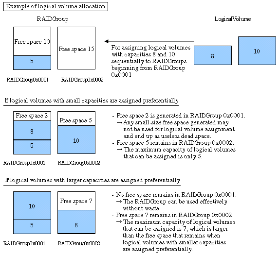
LogicalVolume assignment areas within a RAIDGroup
When two or more free spaces exist in a RAIDGroup, LogicalVolumes are assigned preferentially beginning from an area with smaller free space. Doing so enables the effective and efficient use of a RAIDGroup.
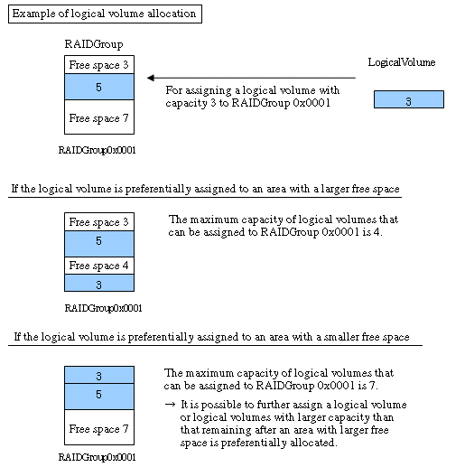
RAIDGroup allocation order
A RAIDGroup is allocated according to LogicalVolume assignment as shown below. The RAIDGroup to be used can also be selected from a list of existing RAIDGroups.
[Distribution to individual RAIDGroups]
A RAIDGroup with the smallest allocation to LogicalVolumes is allocated preferentially.
Distributing LogicalVolumes to RAIDGroups can distribute loads. If two or more RAIDGroups have the same size of LogicalVolume allocation, the one with the smallest RAIDGroup number is allocated preferentially.
[Order of RAIDGroup numbers]
RAIDGroups with smaller numbers are allocated preferentially.
Configuring a RAIDGroup (only when RAIDGroup configuration permission is given)
The automatic configuration function configures a RAIDGroup by selecting disks evenly from individual groups to secure availability.
The configurations of LogicalVolumes and RAIDGroups created by the automatic configuration function are automatically correctable. The following operations are manually available.
Create and delete RAID groups, and add and delete disks.
Create and delete LogicalVolumes.
Create and delete hot spares.
The above operations make it possible to create rough configurations at a time by the automatic configuration function and make correction of details by manual configuration.
Storage Volume Configuration Navigator designs and sets a storage device configuration according to the following steps:
Starting (offsite)
Start Storage Volume Configuration Navigator by selecting it from the Start menu or clicking the corresponding desktop icon.
Loading the device configuration
If the real device configuration has been saved in advance to a file onsite, load the file. In this case, steps 3, "Creating a device unit," and 4, "Mounting disks," does not need to be performed.
Creating a device unit
Click the icon of the device, whose configuration is to be designed and set, from the unit stencil to create a device unit on the design window. For more information, see "11.2.6 Creating a device unit (for new designing offsite) ".
Mounting disks
Mount disks according to the real device configuration in the device unit. If a required DE has not been mounted on the location where a disk is to be mounted, mount a DE first. For more information, see "11.2.7 Mounting disks (for new designing offsite) ".
Configuring RAIDGroups and LogicalVolumes
Configure RAIDGroups and LogicalVolumes in the device unit. Using the automatic configuration function can greatly simplify the designing process. See "11.2.8 Executing automatic configuration" for more information on the automatic configuration function. Manual configuration is also possible. In addition, editable RAID levels and LogicalVolumes in the Storage Volume Configuration Navigator are as follows.Unsupported RAID levels and LogicalVolumes are not editable.
Supported RAID levels
RAID1+0 and RAID1, RAID5 and RAID6 are supported.
However, if an unsupported LogicalVolume (Snap Data Volume excluded) is associated with RAID groups, even a supported RAID level is not editable.
Supported LogicalVolumes
Open Volumes are supported. However, even if it is an Open Volume, a concatenated volume is not supported.
Follow the procedure below for manual configuration:
Configuring RAIDGroups
Configure RAIDGroups in the device unit. For details, see "11.2.9 Creating a RAIDgroup (manual creation) ".
Allocating LogicalVolumes
Allocate LogicalVolumes to the RAIDGroups thus configured. For details, see "11.2.12 LogicalVolume creation (manual operation) ".
Creating a hot spare disk
Create a hot spare disk in the device unit. For details, see "11.2.14 Creating a hot spare disk (manual operation) ".
Creating AffinityGroups and Allocating LUNs
Create AffinityGroups within a device unit to allocate LUNs.
When creating AffinityGroup, LogicalVolumes are required within the device unit.
For details, see "11.2.15 AffinityGroup operation(manual creation)".
Saving as a file
Save the configuration whose design is complete as a file. For details, see "11.2.24 Reading and saving a file".
Starting (onsite)
Start Storage Volume Configuration Navigator by selecting it from the Start menu or clicking the corresponding desktop icon.
Loading the file
Load the file that was saved in Step 7. For details, see "11.2.24 Reading and saving a file".
Login
Log in to the operation management server at Onsite with a privileged administrator.
For details, see "11.2.18 Login".
Entering a serial number
To specify the real device for which the data of the device configuration created in the device unit is to be defined, enter the serial number of the real device in the device unit. For details, see "11.2.19 Entering a serial number" Note that this operation is not required if a device configuration was created by loading the real device configuration from the file.
Device matching
Make sure that the serial number entered in the device unit is correct and define the correspondence between the device unit and the real device on a one-to-one basis. For details, see "11.2.20 Device matching".
Setting the device
Set the data of the device configuration created in the device unit for the real device. For details, see "11.2.21 Device setup".
Access path setting
After setting device configuration data to a real device, an access path can be set through the access path management function. For details of access path management, see "6.3 Access Path Management".
Changing the storage device configuration
For changing hardware configurations such as adding disks or DE of a storage device, it is required to be executed before read operation of the device configuration.
Starting Storage Volume Configuration Navigator and loading the device configuration
Select a registered device on the resource view and then select [To Send]- [Storage Volume Configuration Navigator] from the pop-up menu to start. Or, select [File]-[Storage Volume Configuration Navigator] from the menu of the resource view to start, and drag and drop the device icons displayed on the resource view to the design window of the Storage Volume Configuration Navigator to read the device configuration data.
For details, see "11.2.23 Device loading". In addition, when selecting "Storage Configuration Navigator" from the start menu or desktop icons to start, it is necessary to login with a privileged administrator before drag and drop.
Offsite designing and saving of device configuration data to a file
If you want to perform configuration design at Offsite based on the current Storage device configuration, save in a file the device configuration displayed on the design window. Start the Storage Volume Configuration Navigator at Offsite to design. For details, see "++How to perform and define configuration design in advance at Offsite".
Configuring RAIDGroups and LogicalVolumes
Configure RAIDGroups and LogicalVolumes in the device unit. Using the automatic configuration function can greatly simplify the designing process. See "11.2.8 Executing automatic configuration" for more information on the automatic configuration function. Manual configuration is also possible. In addition, editable RAID levels and LogicalVolumes in the Storage Volume Navigator are as follows. Unsupported RAID levels and LogicalVolumes are not editable.
Supported RAID levels
RAID1+0 and RAID1, RAID5 and RAID6 are supported.
However, if an unsupported LogicalVolume (Snap Data Volume excluded) is associated with RAID groups, even a supported RAID level is not editable.
Supported LogicalVolumes
Open Volumes are supported. However, even if it is an Open Volume, a concatenated volume is not supported.
Follow the procedure below for manual configuration:
Configuring RAIDGroups
Configure RAIDGroups in the device unit. For details, see "11.2.9 Creating a RAIDgroup (manual creation)".
Allocating LogicalVolumes
Allocate LogicalVolumes to the RAIDGroups thus configured. For details, see "11.2.12 LogicalVolume creation (manual operation)".
Creating a hot spare disk
Create a hot spare disk in the device unit. For details, see "11.2.14 Creating a hot spare disk (manual operation)".
Creating AffinityGroups and Allocating LUNs
Create AffinityGroups within a device unit to allocate LUNs.
When creating AffinityGroup, LogicalVolumes are required within the device unit.
For details, see "11.2.15 AffinityGroup operation(manual creation)".
Device matching
Make sure that the serial number entered in the device unit is correct and define the correspondence between the device unit and the real device on a one-to-one basis. For details, see "11.2.20 Device matching".
Setting the device
Set the data of the device configuration created in the device unit for the real device. For details, see "11.2.21 Device setup".
Access path setting
After setting device configuration data to the real device, access path can be set with access path management functions. For details of access path management, see "6.3 Access Path Management".
The Storage Volume Configuration Navigator window configuration is explained below:
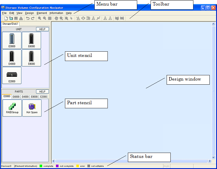
Menu bar
Used to give an operation instruction.
Toolbar
Displays the icons of frequently used functions so that each function can be started simply by clicking the corresponding icon.
Unit stencil
Displays the icons of the devices for which configuration design can be performed. Click the icon of the device for which configuration design is to be started, and the device unit is then displayed on the design window.
Part stencil
Displays the icons of the parts that configure the devices displayed on the unit stencil. Clicking a part icon while selecting the device icon on the design window adds the part to the device unit.
Design window
Used to perform configuration design.
Status bar
Provides examples of status displays on the design window.
This section explains the operations that can be performed from the menu bar, toolbar, and pop-up menus.
|
Menu |
Menu item |
Submenu item |
Toolbar (available/unavailable) |
Pop-up |
Function |
|---|---|---|---|---|---|
|
File |
New creation |
|
Available |
Unavailable |
Starts new configuration design. |
|
Open |
|
Available |
Unavailable |
Opens a device configuration file that has been saved previously. |
|
|
Save |
|
Available |
Unavailable |
Saves the device configuration data to the current file in overwrite mode. |
|
|
Save as |
|
Unavailable |
Unavailable |
Saves the device configuration data to a new file with a name assigned. |
|
|
Page setup |
|
Unavailable |
Unavailable |
Sets the print page. |
|
|
|
|
Available |
Unavailable |
Prints the design window. |
|
|
Quit(X) |
|
Unavailable |
Unavailable |
Quits the window. |
|
|
Edit |
Undo |
|
Available |
Unavailable |
Returns the edit state one state prior. |
|
Redo |
|
Available |
Unavailable |
Returns the edit state one state subsequent. |
|
|
View |
Zoom |
In |
Available |
Unavailable |
Enlarges the display magnification. |
|
Out |
Available |
Unavailable |
Reduces the display magnification. |
||
|
Fit |
Available |
Unavailable |
Automatically adjusts the screen display magnification according to the size of the screen. |
||
|
Hand tool |
|
Available |
Unavailable |
Used to grasp the display on the design window to move (scroll) the display. This item is not displayed on the menu bar. |
|
|
Marquee tool |
|
Available |
Unavailable |
Displays the specified range on the screen. This item is not displayed on the menu bar. |
|
|
Interactive zoom |
|
Available |
Unavailable |
Enables changing the screen display magnification by moving the mouse cursor up and down. This item is not displayed on the menu bar. |
|
|
Selection tool |
|
Available |
Unavailable |
Normal cursor. This item is not displayed on the menu bar. |
|
|
Layout |
Hierarchical |
Available |
Unavailable |
Automatically optimizes the layout of the devices and elements displayed on the design window. Selecting this menu after manually changing the layout or display elements can rearrange the display so that relationships between elements can be checked with ease. |
|
|
Circular |
Available |
Unavailable |
|||
|
Orthogonal |
Available |
Unavailable |
|||
|
Tree |
Available |
Unavailable |
|||
|
Symmetric |
Available |
Unavailable |
|||
|
Orthogonal Line Mode |
|
Unavailable |
Unavailable |
When this mode is selected, the lines connecting the elements in the device are displayed as straight lines, similarly to a circuit diagram. This mode is effective for allowing compact display when a large number of elements are displayed. Selecting this menu again cancels this mode. |
|
|
Tool Bar |
|
Unavailable |
Unavailable |
Selects Show/Hide of the toolbar. |
|
|
Overview(S) |
|
Unavailable |
Unavailable |
Opens the window displaying the entire configuration data controlled on the design window. In overview mode, not only can the display range of the design window be displayed, but also can a range of the design window to be displayed be specified by using the mouse. |
|
|
Design |
Log in |
|
Unavailable |
Unavailable |
Logs in to the administrative server. |
|
Auto Configuration(W) |
|
Unavailable |
Available |
Starts the automatic configuration function. |
|
|
Verification All |
|
Available |
Unavailable |
Checks the configuration for problems. |
|
|
Make LogicalVolume |
|
Unavailable |
Available |
Makes a LogicalVolume in the RAIDGroup. |
|
|
Delete |
|
Unavailable |
Available |
Deletes the selected device unit or part. |
|
|
Copy Device |
|
Unavailable |
Available |
Copies a selected deice unit. |
|
|
Disk Operation |
|
Unavailable |
Available |
Mounts a disk or DE. |
|
|
RAIDGroup Operation |
|
Unavailable |
Available |
Configures a RAIDGroup. |
|
|
AffinityGroup |
|
Unavailable |
Available |
Creates AffinityGroup. This item cannot run under ETERNUS3000, ETERNUS6000, ETERNUS4000 Model 80, 100. |
|
|
Input Serial Number |
|
Unavailable |
Available |
Enters a serial number for the newly created device unit. |
|
|
Device Matching(R) |
|
Unavailable |
Available |
Defines the correspondence between device configuration data and a real device. |
|
|
Cancel Device Matching |
|
Unavailable |
Available |
Cancels device matching performed previously. |
|
|
Device Setup |
|
Available |
Unavailable |
Applies device configuration data to the device. |
|
|
Path search |
|
Available |
Unavailable |
Executes path search. This item is not displayed on the menu bar. |
|
|
Path search clear |
|
Available |
Unavailable |
Clears the result of path search. This item is not displayed on the menu bar. |
|
|
Element |
Detail |
Expand(E) |
Unavailable |
Available |
Used to specify whether to display the elements in the device unit. Select [Expand] to display detail elements. If [Collapse] is selected, detail elements are not displayed but only the icon of the device unit is displayed. |
|
Collapse(C) |
Unavailable |
Available |
|||
|
Table Element(F) |
ON(E) |
Unavailable |
Available |
Displays the integrated element icon selected by the mouse as table elements. When [ON] is selected, table elements are displayed as an integrated element icon. When [OFF] is selected, the integrated element icon is displayed as table elements. |
|
|
OFF(C) |
Unavailable |
Available |
|||
|
Table Element Magnification |
|
Unavailable |
Unavailable |
Changes the display magnifications of all table elements. |
|
|
Property |
|
Unavailable |
Available |
Displays the properties of the selected elements. |
|
|
Information |
Disk Map |
|
Unavailable |
Available |
Displays disk allocation information. |
|
Help |
Help |
|
Unavailable |
Unavailable |
Displays the User's Guide. |
|
Message Reference |
|
Unavailable |
Unavailable |
Displays the Messages. |
|
|
Version Information |
|
Unavailable |
Unavailable |
Displays client information. |
*1 Only a privileged administrator can login.
*2 The user must login as a privileged administrator to execute operation.
The unit stencil displays the icons of devices for which device configuration data can be newly created.
|
Icon |
Device name |
Explanation |
Remarks |
|---|---|---|---|
|
|
ETERNUS3000 |
Used to create an ETERNUS3000(Except for Model 50) device unit. |
(*1) |
|
|
ETERNUS6000 |
Used to create an ETERNUS6000 device unit. |
(*1) |
|
|
ETERNUS4000 |
Used to create an ETERNUS4000 device unit. |
(*1) |
|
|
ETERNUS8000 |
Used to create an ETERNUS8000 device unit. |
(*1) |
|
|
ETERNUS2000 |
Used to create an ETERNUS2000 device unit. |
(*1) |
*1 If a device registered on the resource view is selected and started by selecting [To Send]-[Storage Volume Configuration Navigator] from the popup menu, only the device selected at start-up is operated.
The part stencil displays the icons of the parts that can be added to device units.
|
Icon |
Part name |
Explanation |
Remarks |
|---|---|---|---|
|
|
RAIDGroup |
Used to create a RAIDGroup. |
|
|
|
Hot spare |
Used to create a hot spare disk. |
|
The state of each resource on the design window is indicated using color coding.
|
Color |
Target |
Explanation |
Remarks |
|---|---|---|---|
|
Green |
Device unit |
Device setting is complete. |
|
|
Violet |
Device unit |
Device setting is incomplete, or the device configuration is being edited. |
|
|
Yellow |
Device unit |
Device setting failed. |
|
|
Gray |
Device unit and element |
This device unit or element cannot be edited. |
|
Storage Volume Configuration Navigator can be started using any one of the three methods below:
Select a device registered on the resource view, and then select [To Send]-[Storage Volume Configuration Navigator] from the pop-up menu (*1).
Select [File]-[Storage Volume Configuration Navigator] from the resource view.
Click the icon of Storage Volume Configuration Navigator installed in the client (hereafter referred to as standalone start)
If a device registered on the resource view and started by selecting [To Send] -[Storage Configuration Navigator] from the pop-up menu, a device reading screen is displayed that specifies how to read the specified storage device into the design window. According to the screen, read the device configuration data to work on device configuration design.
Select [File] - [Quit(X)] to exit the Navigator.
In addition, if a device registered on the resource view is selected and started by selecting [To Send]-[Storage Volume Configuration Navigator] from the pop-up menu, the Storage Configuration Navigator will automatically exit by closing the dialog displayed when configuration is not let to read or cannot be read. Also, both when the Storage Volume Configuration Navigator is started from the previous operation and when the Storage Volume Configuration Navigator is started by selecting [File]-[Storage Volume Configuration Navigator] from the menu on the resource view, it will automatically exit by closing the dialog displayed in the same way even when start-up is not enabled.
* 1: If a device registered on the resource view is selected and started by selecting [To Send]-[Storage Volume Configuration Navigator] from the pop-up menu, it is necessary to select the device on the resource view in advance and execute [Register]-[Register SAN devices] from the pop-up menu.
To design a new device configuration, first create the device unit to be designed on the design window. To do so, click the target device icon on the unit stencil as shown in the figure below.

When the device icon is clicked, a device creation window appears as shown below:
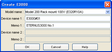
Enter the necessary information in the window.
Select the device model from the dropdown menu of [Model name].
A model number ending with "*" (example: E320R10*) can be used as a device having the same model number before the "*".
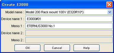
Enter the name of the target device in the [Device name 1] field. The device name entered here is a temporary name used for identification on the design window. Executing the device matching operation replaces the name with the one defined on the administrative server. [Device name 2] is enabled only when a dual configuration model is specified. Enter the name of a device. The specified name is assigned to each of the duplicated devices.
Enter a memo in [Memo 1] as necessary. The memo information entered here is a memo on the design window and cannot be referenced on the resource view after a configuration is set for the device. [Memo 2] is enabled only when a dual configuration model is specified. Enter memo information.
Click the [OK] button.
The above operations create a device unit on the design window. Continue to perform the disk mount operation and then execute the automatic configuration function to automatically configure a RAIDGroup and LogicalVolumes. A RAIDGroup and LogicalVolumes can also be configured manually.
This section explains how to add a disk to the device unit and how to delete a disk from the device unit.
If the automatic configuration function is used to automatically configure a RAIDGroup and LogicalVolumes for the device unit that has been newly created, disks must be added in advance by this procedure according to the configuration of the real device.
This is because the automatic configuration function makes a configuration within the range of the disks already mounted. Disks must also be added in advance by this procedure even in cases where a RAIDGroup is to be configured manually.
A disk can also be added to, or deleted from, the real device unit displayed with the device load operation.
When a volume shortage occurs during operation, for instance, a RAIDGroup and LogicalVolumes need to be created. If free disks are required to create them do not exist, the required disks must be added to the real device. To be prepared for this type of situation, the user can use the procedure explained here to add disks to the disk mount positions and then execute the automatic configuration function or configure a RAIDGroup and LogicalVolumes manually. Doing so enables the user to create in advance the device configuration after disk addition without actually adding disks to the real device.
Mount a disk according to the following procedure:
While selecting a device unit, select [Design] - [Disk Operation] from the menu bar or select [Disk Operation] from the popup menu to open the disk operation window. The figure below shows how the disk operation window is opened.
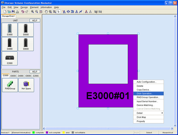
Check whether a DE is already mounted at the position where a disk is to be mounted. If not, mount a DE by following the procedure below. If a DE is already mounted, this operation is not required.
To delete an existing DE, select the [Select DE] check box, and click the [Delete] button.
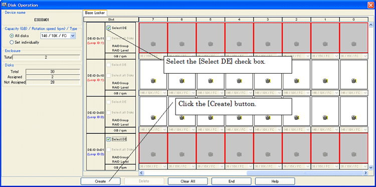
Specify the type of the disk to be mounted. The disk type can be specified either for all disks (All disks) or for individual slots (Set individually).Select either [All disks] or [Set individually] from [Capacity(GB)/Rotation speed(rpm)/Type].When [All disks] is selected, click the down arrow and select the type of the disks to be added. When [Set individually] is selected, select the type of the disk to be added to each disk slot. Disk types are displayed as follows:
|
Description on the screen |
Disk type name |
|
FC |
Fibre Channel Disk |
|
FC(N) |
Nearline FC Disk |
|
SAS |
SAS Disk |
|
SATA(N) |
Nearline SATA Disk |
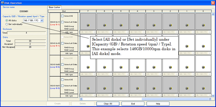
After specifying the disk type, specify the position where the disks are to be mounted. The disk mount position can be specified either for all disk mount positions in a DE or for individual slots. After specifying the disk mount positions, click the [Create] button. The figure below shows how disks are mounted.
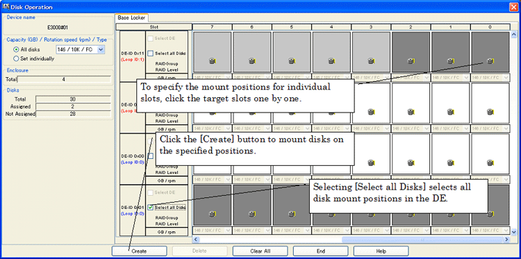
To delete a disk, select the disk and click the [Delete] button.
The automatic configuration function can be used to automatically configure LogicalVolumes. This function automatically allocates a RAIDGroup and LogicalVolumes in an optimum configuration for the device unit. Automatic configuration is enabled for both a device unit created from the unit stencil and a device unit loaded from the real device with the device load function. For either type of device unit, automatic configuration can be performed even after the device configuration is changed by disk operation or RAIDGroup operation. The device configuration created by automatic configuration can also be reconfigured manually.
The following explains how to operate the automatic configuration function.
While selecting a device unit, select [Design] - [Auto Configuration(W)] from the menu bar or select [Auto Configuration] from the popup menu to open the disk operation window. The figure below shows how the disk operation window is opened.
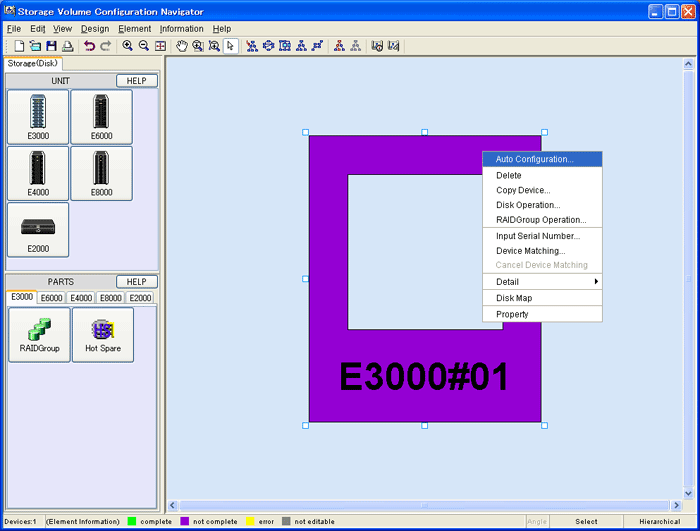
Enter the necessary information on the auto configuration window. The auto configuration window is shown below.
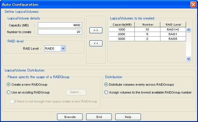
The following explains the meanings of individual parameters and how to use the window.
Define LogicalVolumes
Enter information on the LogicalVolumes to be created. Specify the capacity of a LogicalVolume for [Capacity(MB)]. Specify the number of LogicalVolumes to be created for [Number of create]. For [RAID Level], select the RAID level of the RAIDGroup to which the LogicalVolumes are to be assigned. After specifying the above parameters, click the [>>] button to move the specified LogicalVolume parameters to [LogicalVolumes to be created]. To delete a LogicalVolume parameter from [LogicalVolumes to be created], select the corresponding field and click the [<<] button.
LogicalVolume Distribution
Specify how the RAIDGroup and LogicalVolumes are to be configured.
LogicalVolume assignment method
Select a volume assignment method in [Please specify the usage of a RAIDGroup]. In other words, specify the RAIDGroup to which the LogicalVolumes specified in [Define LogicalVolumes] are to be assigned. Select one of the following two methods:
[Create a new RAIDGroup]
No existing RAIDGroups are used but free disks are used to create a RAIDGroup, after which the LogicalVolumes are assigned to the created RAIDGroup.
[Use an existing RAIDGroup]
LogicalVolumes are assigned by searching the existing RAIDGroups for free space. Clicking the [Select] button lists existing RAIDGroups. The user can uncheck a certain RAIDGroup to prevent it from being allocated to LogicalVolumes. (*1) If the option "If there is not enough free space create a new RAIDGroup" is selected, a new RAIDGroup is created for allocating LogicalVolumes only when the existing RAIDGroups run short of free space.
*1: RAID groups that cannot be edited with Storage Volume Configuration Navigator are not displayed (for more information, see "11.1.4 Operation procedure").
LogicalVolume assignment method
Select one of the options under [Distribution]
When [Distribute volumes evenly across RAIDGroups] is selected, LogicalVolumes are assigned to target RAIDGroups as evenly as possible.
When [Assign volumes to the lowest available RAIDGroup number] is selected, LogicalVolumes are assigned in order of RAIDGroup numbers.
After entering all necessary parameters, click the [Execute] button.
This completes the procedure for automatically allocating LogicalVolumes.
Select a device unit and click a RAIDGroup icon on the part stencil to open the RAIDGroup operation window. Alternatively, select a device unit and select [Design] - [RAIDGroup Operation] from the menu bar or select [RAIDGroup Operation] from the popup menu to open the RAID group operation window. The RAIDGroup operation window is shown below.
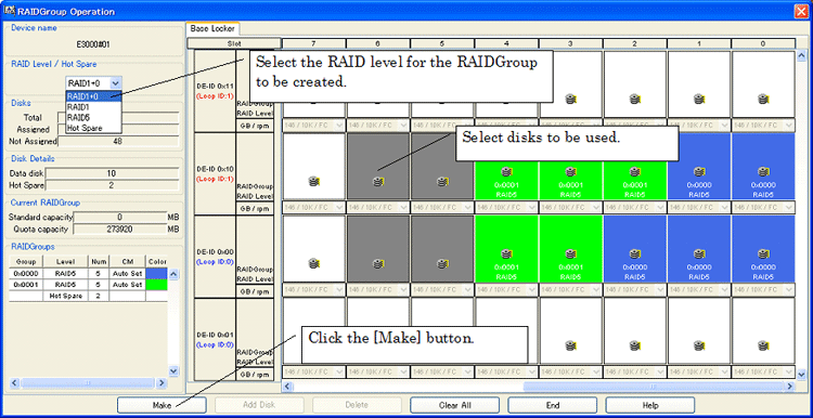
In the RAID group operation window displayed, create a RAID group as follows:
Select the RAID level of the RAIDGroup to be created. Select the RAID level from [RAID Level / Hot Spare]. If [Hot Spare] is selected here, a hot spare disk can be created.
Select the disks to be used. Clicking the button representing a disk puts the disk in the selected state, and clicking the button again deselects the disk.
After selecting all necessary disks, click the <Make> button.
This completes the procedure for creating the specified RAIDGroup or hot spare disk.
To add a disk to a RAIDGroup, select the target RAIDGroup on the design window and select [Design] - [RAIDGroup Operation] from the menu bar or select [RAIDGroup Operation] from the popup menu. The RAIDGroup operation window is shown below.
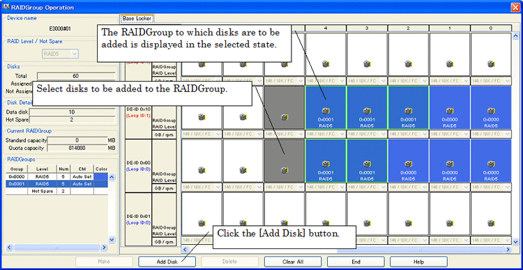
The RAIDGroup operation window opens with the activated RAIDGroup displayed in the selected state. Add a disk to the RAIDGroup as follows:
Select the disk to be added to the RAIDGroup.
Click the [Add Disk] button.
This completes the procedure for adding the specified disk to the RAIDGroup.
To delete a RAIDGroup, select the RAIDGroup to be deleted from the design window and select [Design] - [Delete] from the menu bar or select [Delete] from the popup menu. Gray LogicalVolumes cannot be deleted.
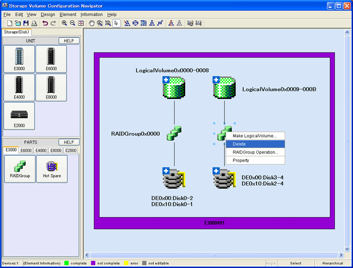
Select the RAIDGroup in which a LogicalVolume is to be created, and select [Design] - [Make LogicalVolume] or select [Make LogicalVolume] from the popup menu to open the LogicalVolume creation window.
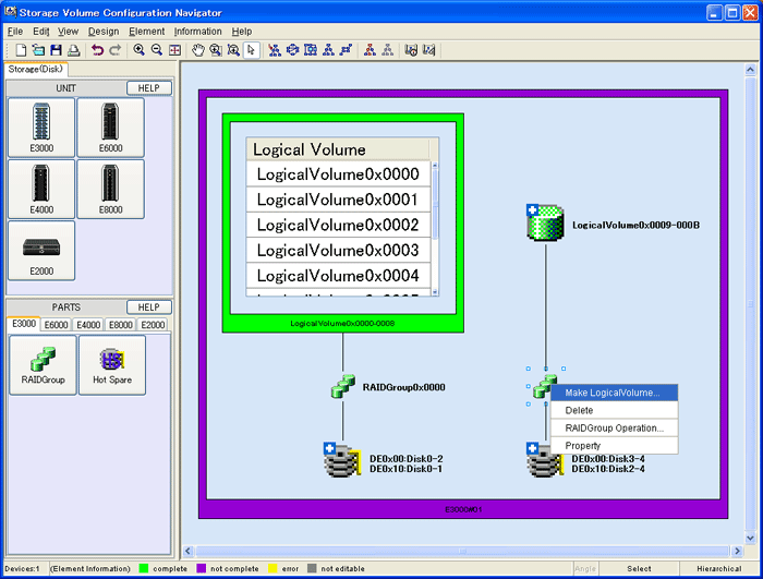
The LogicalVolume creation window is shown below:
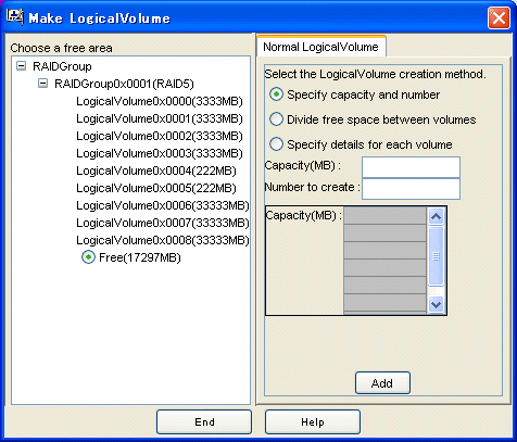
Create a LogicalVolume using the LogicalVolume creation window as follows:
From the RAIDGroup tree, select the free space to be allocated to a new LogicalVolume.
Select one of the following three methods of LogicalVolume creation:
[Specify capacity and number]
Specify the capacity of a LogicalVolume for [Capacity(MB)] and the number of LogicalVolumes for [Number to create].
[Divide free space between volumes]
The LogicalVolume capacity is allocated evenly according to the number specified for [Number to create] in the specified free space areas.
[Specify details for each volume]
The capacity of the LogicalVolumes to be allocated is entered only once to create LogicalVolumes.
After entering all necessary parameters for creating LogicalVolumes, click the [Add] button.
This completes the procedure for assigning LogicalVolumes to the specified RAIDGroup.
To delete a LogicalVolume, select the LogicalVolume to be deleted from the design window and select [Design] - [Delete] from the menu bar or select [Delete] from the popup menu. Gray LogicalVolumes cannot be deleted. The figure below shows how a LogicalVolume is deleted.

While selecting a device unit, click the Hot Spare icon on the part stencil to open the hot spare disk operation window. The hot spare disk operation window is shown below.
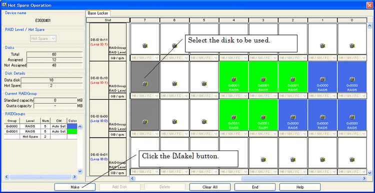
Create a hot spare disk using the hot spare disk operation window as follows:
Select the disks to be used. Clicking the button representing a disk puts the disk in the selected state, and clicking the button again deselects the disk.
After selecting all necessary disks, click the [Make] button.
This completes the procedure for creating a hot spare disk. A hot spare disk can also be created using the RAIDGroup operation window.
Select a device unit and then select [Design] - [AffinityGroup Operation] from the menu or [AffinityGroup Operation] from the pop-up menu to start the AffinityGroup operation window.The AffinityGroup operation window is shown below.AffinityGroup cannot be operated by ETERNUS3000, ETERNUS6000, ETERNUS4000 Model 80 and Model 100.
Setting AffinityGroup in the Storage will allow it to set an access path by access path management functions. For access path management, see "6.3 Access Path Management"
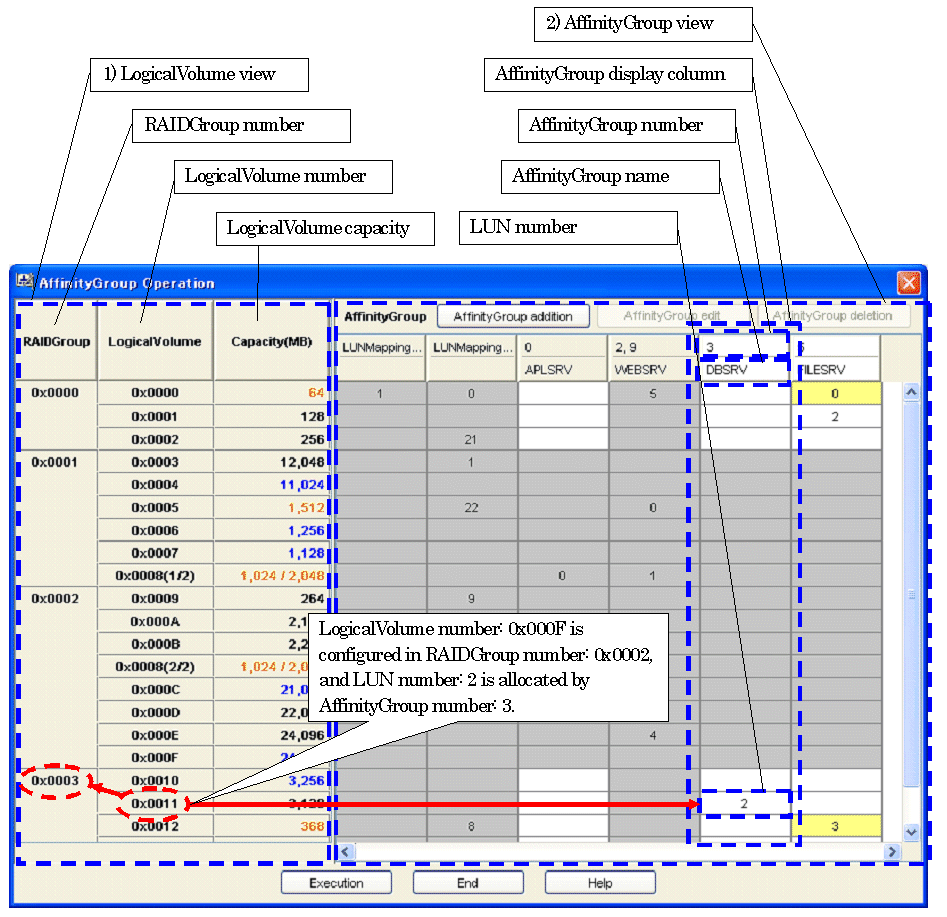
The following are descriptions of the configuration of the AffinityGroup operation window.
LogicalVolume view
A LogicalVolume view is displayed that is configured in the device unit selected at start-up of the Affinity operation window
RAIDGroup number
RAIDGroup numbers are displayed. RAIDGroups to which LogicalVolumes are not allocated are not displayed
LogicalVolume numbers
A LogicalVolume numbers is displayed by RAIDGroup.
To a LogicalVolume to which LUN concatenation is executed is displayed [(Serial number/LogicalVolume concatenated total number)], following the LogicalVolume number.
e.g.: If 0x0008(1/2) is displayed, a LogicalVolume Number is 0x0008, a serial number is 1 and a LogicalVolume concatenated total number is 2.
LogicalVolume capacity
The capacity of LogicalVolume is displayed. The unit is MB.
Depending on the allocation to AffinityGroups, font colors vary as follows.
|
Font color |
Meaning |
|
Black |
Allocated |
|
Blue |
Unallocated |
|
Orange |
Allocated to multiple AffinityGroups or to LUNMapping. (shared with LogicalVolume) |
A LogicalVolume to which LUN concatenation is executed is shown in [relevant amount/totoal amount].
AffinityGroup view
The views of AffinityGroups and LUNMappings are displayed that are configured in the device unit selected at start-up of the AffinityGroup operation window.
AffinityGroup number
AffinityGroup numbers are displayed in decimal. If AffinityGroups are concatenated, all the numbers of concatenated AffinityGroups are displayed set off with commas.
For LUNMappings, port names are displayed.
AffinityGroup name
Aliases of AffinityGroups and LUNMappings are displayed.
LUN number
A LUN number allocated to the LogicalVolume in a LogicalVolume view in the same row is displayed in decimal by AffinityGroup and by LUNMapping.
The cell color changes as follows depending on the relevant LogicalVolume state.
|
Cell color |
Meaning |
|
White |
LUN number is editable. Also, a relevant LogicalVolume is not allocated to multiple AffinityGroups or LUNMappings (Multiple LUN numbers are not allocated). |
|
Yellow |
LUN number is editable. Also, a relevant LogicalVolume is allocated to multiple AffinityGroups or LUNMappings (Multiple LUN numbers are Allocated). |
|
Gray |
LUN number is not editable. If a LUN number falls under the following, it is not editable. LogicalVolume of a type that is not supported by the Storage Volume Configuration Navigator. LUNMapping Concatenated AffinityGroup |
The following are descriptions of operation procedures of the AffinityGroup operation window.
[AffinityGroup addition]
Press the <AffinityGroup addition> button on the AffinityGroup operation window.
Then, the AffinityGroup add dialog is displayed. Enter a group number and a group name. Group names are optional.
Press the <OK> button.
Once the maximum number of AffinityGroups has been created no more can be added.
[Allocating LUN and changing LUN number]
If you want to allocate a LUN (or change a LUN number), focus on a cell at which a row of LogicalVolume and a column of AfiinityGroup are intersected.
Enter the LUN number you want to allocate.
[Automatic allocation of LUN]
Select multiple cells to which you want to allocate LUNs and at which multiple rows of LogicalVolume and multiple columns of AffinityGroup are intersected.
Select [Automatic allocation] from the pop-up menu displayed by right click of mouse.
For automatic allocation of LUN, LUN numbers are allocated in ascending order from the smallest LUN number that is not allocated in the relevant AffinityGroup.
[Unallocating LUN]
Focus on a cell to which you want to unallocated a LUN and at which a row of LogicalVolume and a column of AffinityGroup are instersected.
Press the delete key or the backspace key.
You cannot create any AffinityGroup without LUN.
[Unallocating multiple LUNs]
Drag multiple cells to which you want to unallocated LUNs and at which multiple rows of LogicalVolume and multiple columns of AffinityGroup are intersected.
Select [Unallocation] from the pop-up menu displayed by right click of mouse.
You cannot create any AffinityGroup without LUN.
[Changing AffinityGroup number and AffinityGroup name]
Press the <AffinityGroup edit> button with an AffinityGroup number or an AffinityGroup name you want to change selected. Or, select [AffinityGroup edit] from the pop-up menu.
Then the AffinityGroup change dialog is displayed. Enter a desired group number and a desired group name.
Press the <OK> button.
In the following case, AffinityGroup number is not changeable.
AffinityGroup to which a host affinity is set.
In the following cases, AffinityGroup numbers and AffinityGroup names are not changeable.
AffinityGroup to which a LogicalVolume is allocated that is allocated to an unsupported RAIDGroup.
AffinityGroup to which an unsupported LogicalVolume is allocated.
Concatenated AffinityGroup.
LUNMapping
[Deleting AffinityGroup]
Press the <AffinityGroup deletion> button with an AffinityGroup number or an AffinityGroup name you want to delete selected. Or select [AffinityGroup deletion] from the pop-up menu.
Then the confirmation dialog to delete AffinityGroup is displayed. If it is all right, press the <OK> button.
In the following cases, AffinityGroups cannot be deleted.
AffinityGroup to which a LogicalVolume that is allocated to an unsupported RAIDGroup is allocated.
AffinityGroup to which an unsupported LogicalVolume is allocated.
Concatenated AffinityGroup
AffinityGroup to which a host affinity is set.
LUNMapping
[Reflecting to the design window]
If you want to reflect created or corrected contents to the design window, press the <Execution> button.
Whenever the <Execution> button is pressed on the design window after the AffinityGroup operation window exits, the Return/Redo commands are executable.
[Exiting the operation window]
To exit the AffinityGroup operation window, press the <End> button. If the <End> button is pressed before the <Execution> button, created or corrected contents are not reflected to the design window but the window exits.
This function allows you to efficiently create a device configuration containing similar device units. First create an original device unit, use Copy Device to copy as many device units as desired, and then edit the devices (*1). Copy Device can be operated as shown below.
Selecting an original device unit of which you want to make a copy, select "Copy Device" from the menu bar and pop-up menu. The following Copy Device window then appears.

Enter the name you want to assign to a copied device unit in the [Name] text box. This is a temporary name used for identifying the device on the design window. The device matching operation renames the temporary names as device names specified in the operation management server.
Write any necessary information in the [Memo] text box. This memo information is only valid on the design window. You cannot browse this information on the resource view after configuring the devices.
Click [OK].
With these operations, the copied device unit is now created on the design window. Now you can edit the configuration.
*1 If a device registered on the resource view is selected and started by selecting [To Send]-[Storage Volume Configuration Navigator] from the pop-up menu, only the device selected at start-up is operable.
Storage Volume Configuration Navigator can display how disks are currently assigned to a device unit. Select a device unit, and select [Information] - [Disk Map] from the menu bar or select [Disk Map] from the popup menu to open the disk map window. The disk map window is shown below.

When Storage Volume Configuration Navigator is started in standalone mode, the user must login to the operation management server before reading the real device configuration, device matching, and device setting. Select [Design] - [Log in] from the menu bar to open the login window. The login window is shown below.
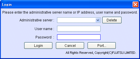
For [Administrative server], enter the address of the administrative server.
For [User name], enter the user name with administrator authority.
For [Password], enter the password.
Click [OK] to login.
If a device registered to the resource view is selected and started by selecting [To Send]-[Storage Volume Configuration Navigator] from the pop-up menu, or started by selecting [File]-[Storage Volume Configuration Navigator] from the menu on the resource view, login operation is not required.
The serial number of the real device must be specified as information required to associate the device unit created virtually with the real device. The device matching operation explained later searches for the real device that matches the serial number entered here, and maps the device unit to the detected real device.
To open the serial number entry window, select a device unit, and select [Design] - [Input Serial Number] from the menu bar or select [Input Serial Number] from the popup menu. The serial number entry window is shown below.
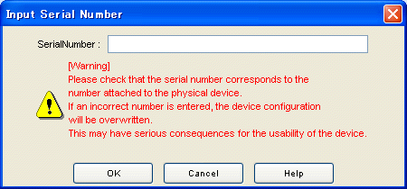

Make sure that the serial number to be entered matches that appearing on the label affixed to the real device. If the serial number of a real device differing from that of the target real device is entered, the device configuration will be destroyed and system operation will be very adversely affected.
Enter a serial number as follows:
Select a virtual device unit displayed on the design window.
Select [Input Serial Number] from the menu.
Enter a serial number.
Click [OK].
The device matching operation checks or specifies the real device to which the settings of the device unit displayed in the edit window should be applied. For a device unit that has been created virtually, execute this operation after entering a serial number. If designing is performed offsite, login as a privileged administrator to the operation management server before executing this operation.
To open the device matching window, select the device unit to be matched, and select [Design] - [Device Matching(R)] from the menu bar or select [Device Matching] from the popup menu. The device matching window is shown below.
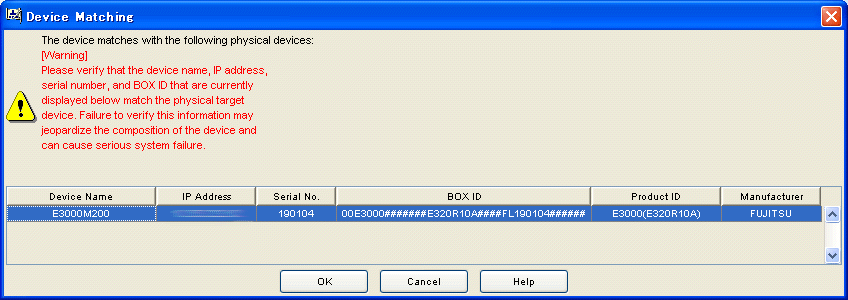

The device matching window displays information on the real device with a serial number that matches the one defined for the device unit selected on the design window. Check the IP address, serial number, and BOX ID displayed to make sure that the device is the right one for which the configuration setting is to be performed.
If a device different from the real target device is selected, the device configuration will be destroyed and system operation will be very adversely affected.
The operation procedure is explained below:
From the list of real devices, select the target device to verify the device matching.
Click [OK] to validate the device matching.
If the device name entered in the device unit creation window differs from that of the real device during device matching, a message indicating that the device name of the real device is to be replaced appears. Similarly, when you select a model number ending with an "*" in the device unit creation window, a message indicating that the product name of the real device is to be replaced also appears. Click the <OK> button.
The device setup operation applies the device configuration of the device unit created on the design window to the real device associated with the device matching operation. To open the device setup window, select [Design] - [Device Setup] from the menu bar, or select the device setup icon from the toolbar. If designing is performed offsite, login as a privileged administrator to the operation management server before executing this operation. The device setup window is shown below.
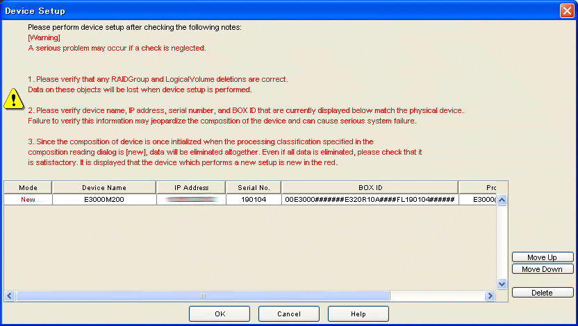
The operation procedure is explained below:
The device configuration is applied sequentially to real devices from the upper to lower of the list. Use the [Move up] and [Move down] button to adjust the order of application. A device that need not be set up can be deleted using the [Delete] button.
Click [OK] to start device setup.

Before starting device setup, be sure to check the following to verify that there are no problems. Failure to do so may cause serious problems.
Depending on the contents of the device configuration, executing device setup deletes a RAIDGroup or LogicalVolume together with the data retained in it. Make sure in advance that the reconfiguration will not cause any problems.
Make sure in advance that the real device to which device configuration data is to be applied is correct. If an incorrect real device is selected for application of device configuration data, the data retained in the real device may be completely destroyed.
When [New] is specified for the process type in the configuration load dialog box, the device configuration is once initialized. Therefore, all data is deleted. Make sure in advance that no problems occur if all data is deleted. "New" is displayed in red for a device for which new setup is to be performed.
After device setup is finished, the device setup result window appears. The data displayed in the device setup result window is as follows:
The device setup result is displayed for each device. The message displayed at [Setup result] is as follows:
|
Message |
Explanation |
Remarks |
|---|---|---|
|
Normal |
Device configuration setting is completed. |
|
|
Unset |
In this configuration, device configuration data cannot be set in the real device. Alternatively, device setup was not performed for this device because an error occurred in a device for which device setup was attempted earlier. |
|
|
Error |
Device setup failed. |
|
The general verification function checks the configuration of the device unit displayed on the design window for problems.
To start general verification, select [General verification] from the menu or click the general verification icon on the toolbar.
The table below provides a summary of what items are checked and what messages are output as the result of checking. Note that device setup is possible even if a warning message with a message number of the type 4xxxxx has been displayed.
|
Checking |
Message No. |
Message text |
|---|---|---|
|
When disks are mounted on the ETERNUS3000, check whether disks are mounted in ascending order of DE numbers in each loop and also in ascending order of slot numbers beginning from 0 in each DE. |
42520, 42521 |
Install disks in order from slot 0, starting with the lower number DEs (loop ID:X). |
|
Check whether the number of disks mounted on the device satisfies the requirements. (ETERNUS3000) |
62531, 62532, 62533, 62535 |
There are insufficient disks. There must be at least X. |
|
Check whether the number of disks mounted on the device satisfies the requirements. (ETERNUS8000, ETERNUS6000, ETERNUS4000, ETERNUS2000) |
62531, 62533, 62536, 62537, 62538, 62541, 62542, 62543, 62546 |
There are insufficient disks. There must be at least X. |
|
Check whether disks are mounted sequentially, without skipping any slot, from the beginning in each DE. (ETERNUS6000) |
42530 |
Install the disks starting with the first one. |
|
Check whether the DEs are mounted continuously. |
42532, 42533 |
The loop ID:X DEs were not installed in sequence. |
|
Check whether the DEs are mounted continuously. (ETERNUS6000) |
42534 |
The DEs were not installed in sequence. |
|
A hot spare disk must be mounted in each loop. Check whether a hot spare disk is missing in any loop. |
42535 |
One loop does not contain a hot spare disk. |
|
When nearline FC disks are mounted, check whether at least 12 nearline disks (except the system disk) are mounted. |
42536 |
Install 12 or more disks that are not nearline FC disks. |
|
When nearline FC disks are mounted, check whether at least 24 nearline disks (except the system disk) are mounted. |
42537 |
Install 24 or more disks that are not nearline FC disks. |
|
When the SAS disk is used for RAID group configuration disk, check whether the hot spare of the SAS disk is mounted. |
42538 |
The hot spare of the SAS disk is not found. |
|
When the nearline SATA disk is used for RAID group configuration, check whether the hot spare of the nearline SATA disk is mounted.(ETERNUS2000) |
42539 |
The hot spare of the nearline SATA disk is not found. |
|
When the fiber channel disk is used for RAID group configuration disk, check whether the hot spare of the fiber channel disk is mounted. |
42540 |
One loop does not contain the hot spare of the fibre channel disk. |
|
When the nearline FC disk is used for RAID group configuration disk, check whether the hot spare of the nearline FC disk is mounted in each loop. (ETERNUS4000, ETERNUS8000) |
42541 |
One loop does not contain the hot spare of the nearline FC disk. |
|
When the nearline SATA disk is used for RAID group configuration disk, check whether the hot spare of the nearline SATA disk is mounted in each loop. |
42542 |
One loop does not contain the hot spare of the nearline SATA disk. |
|
Check whether two or more disks are mounted in each DE. |
62521 |
Install the two data disks in the first slots of the DE. |
|
Check whether the same number of DEs are mounted in individual loops. |
62522 |
The number of DEs is different in loop ID:0 and loop ID:1. |
|
Check whether disks are mounted in Slots 0 to 3 of DE0x00. (ETERNUS3000) |
62523 |
Install disk between slot 0 and 3 in DE0x00. |
|
Check whether DEs are mounted in ascending order of the DE numbers. |
62529 |
DE is not installed in sequence. |
|
Check whether the maximum capacity of the hot spare disk is greater than the maximum capacity of disks related to RAIDGroups. Check this for each loop. |
62530 |
One of the hot spare disks is not working. |
|
Check whether the maximum capacity of the SAS disk defined as hot spare is greater than that of the SAS disk used in RAID Groups. (ETERNUS2000) |
62544 |
Hot spare disk with insufficient capacity found in SAS disk. |
|
Check whether the maximum capacity of theNearline SATA disk defined as hot spare isGreater than that of the nearline SATA diskUsed in RAIDGroups. (ETERNUS2000) |
62545 |
Hot spare disk with insufficient capacity found in nearline SATA disk. |
|
Check for each loop whether the maximum capacity of the fibre channel disk defined as hot spare is greater than that of the fibre channel disk used in RAIDGroups. (ETERNUS4000, ETERNUS8000) |
62547 |
One loop that has hot spare disk with insufficient capacity found in fibre channel disk. |
|
Check for each loop whether the maximum capacity of the nearline FC disk defined as hot spare is greater than that of the nearline FC disk used in RAIDGroups. (ETERNUS4000, ETERNUS8000) |
62548 |
One loop that has hot spare disk with insufficient capacity found in nearline FC disk. |
|
Check for each loop whether the maximum capacity of the nearline SATA disk defined as hot spare is greater than that of the nearline SATA disk used in RAIDGroups. (ETERNUS4000, ETERNUS8000) |
62549 |
One loop that has hot spare disk with insufficient capacity found in nearline SATA disk. |
The device configuration of a storage device is readable from the resource view. When starting up a single device, log in to the operation management server with a privileged administrator before operation.

The operation procedure is explained below:
Select one of the following modes from [Processing mode]:
[Updating]
When configuration data is set in the device, only the updated portions of the data are set in the device.
[New]
The device configuration data edited based on the device configuration that has been loaded is set in the real device after the real device configuration data is initialized. When newly executing device setup, make sure in advance that no LogicalVolumes exist in the real device.
Select one of the following methods from [The reading method]:
[Only object device is read]
Only the device configuration of the specified storage device is loaded.
[Related device is also read]
Configuration data for switches and hosts related to the specified storage device is also read.
Click the [OK] button.
A storage device in one of the following states cannot be loaded:
Storage device whose device status is other than normal or warning
Storage device using a hot spare disk, which means a storage device in one of the following states:
A RAIDGroup is using the hot spare disk.
The storage device is being copied back.
The storage device is being rebuilt.
Storage device within which a LogicalVolume of LUN concatenation is being created.
Device configuration data created on the design window can be saved by selecting [File]-[Save As] from the menu bar. The device configuration data thus saved can be read by selecting [File]-[Open] from the menu bar. (*1)
*1 If a device registered on the resource view is selected and started by selecting [To Send]-[Storage Volume Configuration Navigator] from the pop-up menu, only the device configuration data is allowed to save.
The operation was attempted while the user was not logged in to the operation management server.
Login to the operation management server and then reexecute the operation.
The authentication information does not match that in the window in which the device to be loaded was specified.
Match the authentication information, and reload the device.
If a device registered on the resource view is selected and started by selecting [To Send]-[Storage Volume Configuration Navigator] from the pop-up menu, reading to the device is allowed by drag and drop.
Perform the device load operation after starting Storage Volume Configuration Navigator by selecting it from the Start menu or by clicking the corresponding desktop icon, or start the storage device by selecting [File] - [Storage Volume Configuration Navigator] from the resource view.
Authentication failed with the entered account information.
Check the user information and password, and then retry the operation.
The specified account information does not indicate a privileged administrator.
Make sure that the account information is of a privileged administrator, and then retry the operation.
The specified operation management server name is not found in the network.
Check the operation management server name, and then retry the operation.
Automatic configuration was executed without entering LogicalVolume information in the auto configuration window.
Enter LogicalVolume information and then execute auto configuration.
An invalid value was specified for the LogicalVolume capacity in the auto configuration window.
Specify a valid value for the LogicalVolume capacity of the LogicalVolume information.
An invalid value was specified for the number of LogicalVolumes in the auto configuration window.
Specify a valid value for the number of LogicalVolumes of LogicalVolume information.
The number of disks is insufficient for creating RAIDGroups to which the specified LogicalVolumes can be assigned.
Add disks to the device.
For a real device, add disks to the real device, execute device loading, and then perform automatic configuration again.
No disks are mounted on the device for which automatic configuration is to be performed.
Mount disks on the device.
For a real device, mount disks on the real device, execute device loading, and then perform automatic configuration again.
The specified capacity of LogicalVolumes exceeds the maximum LogicalVolume capacity that can be assigned to the device.
Specify a smaller value for the LogicalVolume capacity.
The sum of the specified number of LogicalVolumes and the number of existing LogicalVolumes exceeds the maximum number that can be assigned to the device.
Reduce the number of LogicalVolumes to be created.
No DE is mounted on the device. Automatic configuration cannot be executed for a device without a DE.
Mount DEs on the device.
For a real device, modify the real device configuration, execute device loading, and then perform automatic configuration again.
The configuration of the DEs mounted on the device contains an error.
Check and correct the DE configuration of the device.
For a real device, correct the real device configuration, execute device loading, and then perform automatic configuration again.
Disks must always be mounted as backup disks in DE0x00 Slot0 to Slot3.
Perform disk operation to mount disks in DE0x00 Slot0 to Slot3.
For a real device, modify the real device configuration, execute device loading, and then perform automatic configuration again.
Disks are not mounted in DE0x10 or expansion DE Slot0 and Slot1.
Perform disk operation to mount disks in DE0x10 or expansion DE Slot0 and Slot1.
For a real device, modify the real device configuration, execute device loading, and then perform automatic configuration again.
A hot spare disk could not be secured because any disk has a free space exceeding the largest disk capacity, from among the disks already allocated to the RAIDGroup.
Perform disk operation to mount a disk having a free space exceeding the largest disk capacity among the disks already allocated to the RAIDGroup.
For a real device, modify the real device configuration, execute device loading, and then perform automatic configuration again.
The current capacity of the existing RAIDGroups is insufficient for assigning the specified LogicalVolumes.
Perform RAIDGroup operation to create a RAIDGroup and then execute automatic configuration. Alternatively, execute automatic configuration by specifying that a new RAIDGroup be created.
Data disks must be mounted in the first two slots of each DE.
Perform disk operation to mount data disks in the first two slots of each DE. System disks are not included.
For a real device, modify the real device configuration, execute device loading, and then perform automatic configuration again.
The number of LogicalVolumes exceeds the maximum number of LogicalVolumes that can be assigned to a RAIDGroup.
Reduce the number of LogicalVolumes to a number that can be assigned to a RAIDGroup.
Disks used as backup disks and system disks cannot be used for hot spare disks.
Specify disks other than backup disks and system disks as hot spare disks.
The specified disk cannot be defined as a hot spare disk because its capacity is too small.
For the ETERNUS3000, specify the disk having the largest capacity, from among those mounted on the device.
For the ETERNUS6000, ETERNUS4000 and ETERNUS8000, specify a disk of the same Loop and of the maximum capacity.
For a RAID5 configuration of the ETERNUS6000, disks must be selected on the same DA.
Select disks on the same DA. For information about the DA configuration, refer to the ETERNUS6000 SA/SE Handbook.
A required device name has not been specified.
Specify a device name.
An existing device has the same name.
Specify a unique name.
The RAIDGroup does not have sufficient free space for creating the specified LogicalVolumes.
Reduce the LogicalVolume capacity.
An attempt was made to create more RAIDGroups than permitted in the device.
Create RAIDGroups within a range not exceeding the maximum number permitted in the device.
An unsupported disk is mounted on the real device.
Remove the unsupported disk from the real device, and then reload the device.
The disks configuring of a RAIDGroup are not allocated evenly between loops.
Select the disks configuring a RAIDGroup again so that they are allocated evenly.
The RAIDGroup does not have sufficient free space for creating as many LogicalVolumes as specified.
Create LogicalVolumes in a RAIDGroup that has sufficient free space.
An odd number of disks were specified although a RAIDGroup with RAID level RAID1+0 must be created with an even number of disks.
Specify an even number of disks to create a RAIDGroup, or add disks so that the total number of disks making up a RAIDGroup is an even number.
The selected disks do not meet a configuration recommended for a RAIDGroup. In consideration of performance and reliability, mount four disks each in Loop ID 0 and Loop ID 1.
Mount four disks each in Loop ID 0 and Loop ID 1. Note that this configuration is not always required.
The selected disks do not meet a configuration recommended for a RAIDGroup. Eight or more disks are selected for each loop. In consideration of performance and reliability for this device, assign eight or fewer disks each to Loop ID 0 and Loop ID 1.
Assign eight or fewer disks each to Loop ID 0 and Loop ID 1. Note that this configuration is not always required.
The selected disks do not meet a configuration recommended for a RAIDGroup. In consideration of performance and reliability, mount four disks each in Loop ID 0 and Loop ID 1.
Mount four disks each in Loop ID 0 and Loop ID 1. Note that this configuration is not always required.
The selected disks do not meet a configuration recommended for a RAIDGroup. In consideration of performance and reliability, allocate 16 or fewer disks evenly in each loop.
Allocate 16 or fewer disks evenly in each loop. Note that this configuration is not always required.
The selected disks do not meet a configuration recommended for a RAIDGroup. It is recommended to allocate five disks.
Allocate five disks evenly in each loop. Note that this configuration is not always required.
The specified number of LogicalVolumes to be created causes the total number to exceed the maximum allowable number for the device.
Change the number of LogicalVolumes to be created so that the total number does not exceed the maximum allowable number, and then retry the operation.
The selected disks do not meet a configuration recommended for a RAIDGroup. For RAID5, the recommended configuration consists of five disks, and disks are allocated evenly to loops.
Select five disks for configuring a RAIDGroup in such a way that the disks are allocated evenly to individual loops. Note that this configuration is not always required.
The number of LogicalVolumes to be created is not specified.
Specify the number of LogicalVolumes and then retry the operation.
The LogicalVolume capacity is not specified.
Specify the LogicalVolume capacity and then retry the operation.
The number of selected disks does not meet a configuration recommended for a RAIDGroup. The recommended number of disks is 10.
Select 10 disks. Note that this configuration is not always required.
The capacities of the selected disks are uneven. When the capacities of the disks making up a RAIDGroup are uneven, a RAIDGroup is configured based on the value of the disk with the smallest capacity. Disks with larger capacities cannot be used effectively.
Configure a RAIDGroup with disks having the same capacities. Note that this configuration is not always required. Refer to the SA/SE Handbook for details.
The numbers of rotations of the selected disks are uneven. In this case, a RAIDGroup is configured based on the value of the disk with the smallest number of rotations and this may lead to a performance-related problem. Note that this is not checked if the configuration of a real device has been read from a file.
Configure a RAIDGroup with disks having the same numbers of rotations. Note that this configuration is not always required. Refer to the SA/SE Handbook for details.
The capacities and the numbers of rotations of the selected disks are uneven. If the numbers of rotations making up a RAIDGroup are uneven, a RAIDGroup is configured based on the value of the disk having the smallest number of rotations and a problem may occur in performance. If the capacities are uneven, a RAIDGroup is configured based on the value of the disk with the smallest capacity and disks with larger capacities cannot be used effectively.
Note that this matter is not checked if the configuration of a real device is read from a file.
Configure a RAIDGroup with disks having the same capacities and rotations. Note that this configuration is not always required. Refer to the SA/SE Handbook for details.
The selected disks are not allocated evenly in each loop. Taking performance and reliability into consideration, allocate the disks as evenly as possible.
Select disks again so that the disks are allocated evenly in each loop. Note that this configuration is not always required. Refer to the SA/SE Handbook for details.
Since the selected disks within the DA are both located on the same path, both disks become unusable in case of a failure in the path.
When using disks in the same DA (when the LoopID numbers are displayed in the same color), select disks that are located on different paths. (Select one disk having an even LoopID number and the other having an odd LoopID number.)
The selected number of disks does not meet a recommended configuration. Eight disks are recommended.
Select eight disks and reconfigure the RAIDGroup. Note that this configuration is not always required. Refer to the SA/SE Handbook for details.
For the ETERNUS6000, disks in the same loop cannot be selected to configure RAID1+0.
Select disks from different loops and retry the operation. Refer to the SA/SE Handbook for details.
Deletion failed because deleting disks making up a RAIDGroup results in an unbalanced number of disks in each loop.
Perform deletion so that the numbers of disks in individual loops are equal.
A half or more of the disks configuring a RAIDGroup are specified in one loop. The number of disks assigned to one loop must not exceed half of all disks making up a RAIDGroup.
Specify disks so that the number of disks assigned to one loop is less than half of all disks.
A RAIDGroup containing a LogicalVolume cannot be reconfigured.
Delete the LogicalVolumes and then reconfigure the RAIDGroup.
The selected disks are not allocated as recommended between loops. Distribute disks evenly to loops from the points of view of performance and reliability.
Allocate disks again so that they are distributed evenly to loops. Note that this configuration is not always required.
Recovery from a disk error will not be possible because the capacity of the disk configuring the RAIDGroup exceeds that of the existing hot spare disk.
Assign to a hot spare disk, the disk having a capacity exceeding that of any disk configuring the RAIDGroup.
Recovery from a disk error will not be possible because the capacity of the disk in Loop ID 0 configuring the RAIDGroup exceeds that of the existing hot spare disk.
Assign to a hot spare disk in Loop ID 0, the disk having a capacity exceeding that of any disk in Loop ID 0 configuring the RAIDGroup.
Recovery from a disk error will not be possible because the capacity of the disk in Loop ID 1 configuring the RAIDGroup exceeds that of the existing hot spare disk.
Assign to a hot spare disk in Loop ID 1, the disk having a capacity exceeding that of any disk in Loop ID 1 configuring the RAIDGroup.
Recovery from a disk error will not be possible because the capacity of the disk configuring the RAIDGroup exceeds that of the existing hot spare disk.
Assign to a hot spare disk, the disk having a capacity exceeding that of any disk configuring the RAIDGroup.
When deleting disks configuring a RAIDGroup in the RAID level RAID1+0, delete them so that each loop has the same number of remaining disks.
Perform deletion again so that each loop has the same number of remaining disks.
The number of disks configuring a RAIDGroup in the RAID level RAID1+0 must be an even number.
Perform deletion again so that the number of remaining disks configuring the RAIDGroup becomes an even number.
Deletion failed because the number of disks configuring a RAIDGroup in the RAID level RAID1+0 will be less than the number required for the minimum allowable configuration.
Perform deletion again so that the number of remaining disks does not become smaller than that required for the minimum allowable configuration. For details of the number of disks, refer to the SA/SE Handbook for the respective device.
Deletion failed because the number of disks configuring a RAIDGroup in the RAID level RAID5 will be less than the number required for the minimum allowable configuration.
Perform deletion again so that the number of remaining disks does not become smaller than that required for the minimum allowable configuration. For details of the number of disks, refer to the SA/SE Handbook for the respective device.
A LogicalVolume used by the server cannot be deleted.
Release the LogicalVolume from the server and then delete the LogicalVolume.
The RAIDGroup cannot be deleted because it contains a LogicalVolume that cannot be deleted. Alternatively, the RAIDGroup cannot be deleted because it is not supported.
An attempt was made to delete the RAIDGroup containing a LogicalVolume being used. Check the system configuration.
Using the selected disks exceeds the maximum capacity allowed for a RAIDGroup.
Reduce the number of selected disks or select disks with smaller capacities to configure a RAIDGroup.
The selected disks do not meet a recommended configuration. Selecting a disk featuring the fastest rotation speed in the loop as a hot spare disk prevents degradation of performance when the hot spare disk is incorporated into the RAIDGroup.
Select the disk featuring the fastest rotation speed in the loop and then retry the operation.
The capacities of the disks making up a RAIDGroup are not the same.
(ETERNUS6000)
Select disks making up a RAIDGroup again in such a way that the capacities of individual disks are the same.
The numbers of rotations of the disks making up a RAIDGroup are not the same.
(ETERNUS6000)
Select disks making up a RAIDGroup again in such a way that the numbers of rotations of individual disks are the same.
The capacities and the numbers of rotations are not equal among the disks making up a RAIDGroup.
(ETERNUS6000)
Select disks making up a RAIDGroup in such a way that the capacities and the numbers of rotations are equal among the disks.
This message confirms whether the configuration currently displayed can be abandoned to load a new configuration onto the design window.
If the configuration currently displayed on the design window is required, save the configuration into a file and then perform configuration load operation.
This message confirms whether the configuration displayed on the design window can be overwritten when the device to be loaded is the same as the device unit displayed on the window.
If you do not want to overwrite the configuration on the design window, save the configuration into a file and then perform configuration load operation.
More than one device cannot be selected for device load operation.
Specify one device at a time for device load operation.
The device that was specified for device load operation is not supported.
Perform device load operation by specifying a supported device.
The device in one of the following states cannot be loaded:
1. The status of the device is error.
2. The RAIDGroup is using a hot spare disk.
3. Copy-back is in progress.
4. Rebuilding is in progress.
5. Storage device within which a LogicalVolume of LUN concatenation is being created.
Remove the problem cause and then reload the device.
Exiting was instructed before saving the configuration on the design window.
To save the configuration on the design window, click OK.
An existing device has the same serial number.
Enter a valid serial number.
The device used for device matching is not registered with the operation management server.
Register the relevant device with the operation management server and then retry the operation.
The device with the specified serial number is not registered with the operation management server.
Register the relevant device with the operation management server and then retry the operation.
A device for which device matching has been performed is not found.
Perform device matching and then retry the operation.
No serial number was specified for the device unit.
Specify the serial number and then retry the operation.
No RAIDGroup exists.
Using the automatic configuration function, create a RAIDGroup to which LogicalVolumes can be assigned, and then retry the operation.
This message warns that data will be deleted if a LogicalVolume is deleted.
Make sure that deleting the specified LogicalVolume causes no problems, and then delete it.
Nearline FC disks cannot be used at the selected RAID level.
Confirm disks with which a RAID group of the selected RAID level can be created. For details, refer to the SA/SE handbook.
The selected disk is not configured in the recommended way. For a hot spare disk, select the disk having the largest capacity in the loop.
Select the disk having the largest capacity in the loop, and retry the operation.
A RAIDGroup cannot be created with the selected disk configuration.
Refer to the SA/SE Handbook, and specify a disk configuration with which a RAIDGroup can be created.
The from-copy device unit cannot be copied because it contains an unsupported RAID group. RAID levels of the supported RAID group are RAID1+0, RAID1, RAID5 and RAID6.
Unsupported RAID groups were found in the storage device configuration when loading the device configuration from real devices. Delete the unsupported RAID groups of the real devices, reload the device configuration, and then execute Copy Device again. Otherwise, create a new device unit and make copies of it.
The from-copy device unit cannot be copied because it contains an unsupported linked volume.
Linked volumes were found in the storage device configuration when loading the device configuration from real devices. Delete the linked groups of the real devices, reload the device configuration, and then execute Copy Device again. Otherwise, create a new device unit and make copies of it.
The device cannot be copied because the device unit specified as the copy source contains an unsupported mainframe volume.
Unsupported mainframe volumes are found in the storage device configuration because the device configuration was read from actual devices. Delete the unsupported mainframe volumes in the actual devices, reload the device configuration, and then execute Copy Device again. Or, create a new device unit and execute Copy Device again using the new device as a copy source.
The device cannot be copied because the device unit specified as the copy source is a manual assembly unit or a storage device that cannot be edited.
A manual assembly unit or a storage device that cannot be edited is found in the device configuration because the device configuration was read from actual devices. Create a new device unit and execute Copy Device again using the new device as a copy source.
The file to be opened is not found.
Confirm that the file to be opened exists and try to open it again.
The unsupported format file was saved or opened.
Select a ".cnc" file and try to save or open it again.
The selected device unit cannot be edited. Therefore, you cannot specify the device to add components.
Select the device unit you want to edit on the resource view, load it into Storage Volume Configuration Navigator, and then restart the job.
If a device registered on the resource view is selected and started by selecting [To Send]-[Storage Volume Configuration Navigator] from the pop-up menu, no other storage devices than the storage device specified at start-up are not editable.
Perform the device read operation for the device to be edited by starting Storage Volume Configuration Navigator by selecting it from the Start menu or by clicking the corresponding desktop icon, or start the storage device by selecting [File] - [Storage Volume Configuration Navigator] from the resource view.
No disk can be added in the RAID1 level.
Create a new RAID1.
No more disks can be deleted because doing so puts the number of disks that constitute the RAID group of RAID1 under the minimum configuration.
No disks can be deleted because the current disks are required for the minimum configuration. For details of the number of component disks, refer to the SA/SE Handbook.
Disks in an unsupported RAID level or in a RAID group containing an unsupported LogicalVolume cannot be deleted.
Delete the disks in the unsupported RAID level or in the RAID group containing an unsupported LogicalVolume from the actual device, and then reread the device.
Copy Device failed because the device unit specified as the copy source contained an unsupported MVV volume.
Unsupported MVV volumes are found in the storage device configuration because the device configuration was read from actual devices. Delete the unsupported MVV volumes from the actual devices, reload the device configuration, and then execute Copy Device again. Or, create a new device unit and execute Copy Device again using the new device as a copy source.
Copy Device failed because the device unit specified as the copy source contained an unsupported volume.
Unsupported volumes are found in the storage device configuration because the device configuration was read from actual devices. Delete the unsupported volumes from the actual devices, reload the device configuration, and then execute Copy Device again. Or, create a new device unit and execute Copy Device again using the new device as a copy source.
From the disks specified for Slot0 through Slot3 of DE0x0, there is a disk that cannot be mounted as a backup disk.
Using disk operation, specify a disk that can be mounted as a backup disk. For information on disks that cannot be mounted as a backup disk, refer to the "ETERNUS3000 SA/SE Handbook".
Disks in different pair BRTs (the disks have different Loop ID colors) cannot be selected.
Select disks in the same pair BRT (the disks must have the same Loop ID color), and perform the operation again. For details, refer to the SA/SE handbook.
Disks cannot be added to a RAID group of the selected RAID level.
Create a new RAID group of the selected RAID level.
A disk that is a component of a RAID group of the selected RAID level cannot be deleted.
A disk that is a component of a RAID group of the selected RAID level cannot be deleted.
The RAID group cannot be created by selecting disks with the same Loop ID in a pair BRT (the disks have the same Loop ID color).
Select disks with different Loop IDs in the pair BRT (the disks must have the same Loop ID color), and perform the operation again. For details, refer to the SA/SE handbook.
Disks that are to be paired are selected from the same Loop ID.
Select disks to be paired from the different Loop IDs, and perform the operation again. For details, refer to the SA/SE handbook.
Disks to be paired are selected from the same pair BRT (the disks have the same Loop ID color). Select disks to be paired from different pair BRTs (the disk must have different Loop ID colors).
Perform again the configuration in which disks to be paired are selected from different pair BRTs (the disk must have different Loop ID colors). However, it is not necessary to always use such a configuration. For details, see the SA/SE handbook.
Disks from different Loop IDs are selected. Allocate disks from the same LoopID.
Perform again the configuration in which disks from the same Loop ID are selected. However, it is not necessary to always use such a configuration. For details, see the SA/SE handbook.
Disks from the same Loop ID are selected. Allocate disks evenly from different Loop IDs.
Perform again the configuration in which disks from different Loop IDs are selected evenly. However, it is not necessary to always use such a configuration. For details, see the SA/SE handbook.
Since disks of the same Loop ID are to be paired in this configuration, they cannot be deleted.
Perform the deletion in a way that disks to be paired are of different Loop IDs. For details, see the SA/SE handbook.
Disks to be paired are allocated from the same pair BRT (the disks have the same LoopID color). The recommenced configuration is the one in which disks to be paired are allocated in different pair BRTs (the disk must have different LoopID colors).
Reselect disks in a way that disks to be paired are of different pair BRTs (the disk must have different LoopID colors). However, it is not necessary to always use such a configuration. For details, see the SA/SE handbook.
LogicalVolume was specified with a capacity with which creation is impossible.
Perform the operation in a way that the capacity of the LogicalVolume to be created becomes no less than the minimum capacity. For details, see the SA/SE handbook.
As the number of disks configuring RAID groups in RAID6 becomes larger than the maximum configuration, disks cannot be added.
Disks cannot be added because of the maximum configuration. For details of the maximum configuration, refer to SA/SE handbooks for respective devices.
Disks cannot be deleted because the number of disks configuring RAID groups in RAID6 is less than the minimum configuration.
Disks cannot be deleted because of the minimum configuration. For details of the minimum configuration, refer to SA/SE handbooks for respective devices.
Arrange disks evenly with different LoopIDs.
Retry to make a configuration where disks are evenly selected with different LoopIDs. In addition, it is not always necessary to make this configuration. For details, refer to the SA/SE handbook.
Since an unsupported LUNMapping exists in a device unit specified by copy source, device copy is not allowed.
It is when the configuration is being read from a real device that LUNMapping exists in the configuration of a storage device. After enabling the security setting for FC port on the real device, read the device configuration again to execute device copy.
Since an supported AffinityGroup exists in a device unit specified by the copy source, device copy is not allowed.
It is when the configuration is being read from a real device that a concatenated AffinityGroup exists in the configuration of a storage device. After deleting the concatenated AffinityGroup in the real device, read the device configuration again and execute device copy. In addition, create a new device unit and retry device copy with the device unit as a copy source.
Since a LogicalVolume with an unallocated LUN is allocated to an AffinityGroup, the AffinityGroup cannot be deleted. Or it cannot be deleted because of a concatenated AffinityGroup or a AffinityGroup set by the Host AffinityGroup.
The AffinityGroup or concatenated AffinityGroup to which a LogicalVolume in use is allocated is about to be deleted. Check the system configuration.
The same capacity and speed disk must be installed between slot0 and 3 in DE0x00.
The same capacity and number of rotations of a disk must be specified between slot0 and 3 in DE0x00.
The specified number of disks is not recommended. Recommended composition is 6.
The recommendation is to use 6 as the number of disks; however this is not a requirement.
The disk capacity for the created RAID group configuration is greater than the hot space capacity of the existing same disk type so that a recovery cannot be performed when a disk error occurred.
Define the maximum disk capacity within the device and use SAS and nearline SATA disks as the hot spare.
An attempt was made to install an invalid disk type.
A valid disk type must be specified.
The disk capacity for the created RAID group configuration is greater than the hot space capacity of the existing same disk type and loop.
Specify the applicable maximum disk space for the type of hot spare disk used in the loop.
When disks are mounted on the ETERNUS3000, check whether disks are mounted in ascending order of DE numbers in each loop and also in ascending order of slot numbers beginning from 0 in each DE. A disk that fails to satisfy these conditions exists in Loop ID 0.
Mount disks in ascending order of DE numbers in each loop and also in ascending order of slot numbers beginning from 0 in each DE.
When disks are mounted on the ETERNUS3000, check whether disks are mounted in ascending order of DE numbers in each loop and also in ascending order of slot numbers beginning from 0 in each DE. A disk that fails to satisfy these conditions exists in Loop ID 1.
Mount disks in ascending order of DE numbers in each loop and also in ascending order of slot numbers beginning from 0 in each DE.
Disks are not sequentially mounted (with some slots skipped) from the beginning in each DE. (ETERNUS6000)
Mount disks sequentially without skipping a slot from the beginning of each DE. For details of the disk mounting method, refer to the SA/SE handbook.
DEs are not continuously mounted in Loop ID 0. (ETERNUS3000)
Mount DEs in ascending order of DE numbers in Loop ID 0 without skipping.
DEs are not continuously mounted in Loop ID 1. (ETERNUS3000)
Mount DEs in ascending order of DE numbers in Loop ID 1 without skipping.
DEs are not continuously mounted. (ETERNUS6000)
Mount DEs in ascending order of DE numbers.
Although a hot spare disk must be mounted in each loop, a hot spare disk is missing in a certain loop.
Mount a hot spare disk in each loop.
The number of disks installed in the unit is less than the required number. It is necessary to install required number of disks or more.
When nearline FC disks are mounted, it is necessary that at least 12 nearline disks (except the system disk) be mounted. For real devices, read the devices after correcting the configuration of the real devices. For details, see the SA/SE handbook.
The number of disks installed in the unit is less than the required number. It is necessary to install the required number of disks or more.
When nearline FC disks are mounted, it is necessary that at least 24 nearline disks (except the system disk) be mounted. For real devices, read the devices after correcting the configuration of the real devices. For details, see the SA/SE handbook.
The maximum capacity of the SAS hot spare disk has not been defined.
Define the maximum disk capacity for the SAS hot spare disk.
The maximum capacity of the nearline SATA hot spare disk has not been defined.
Define the maximum capacity for the nearline SATA hot spare disk.
A RAID group loop has been created without a hot spare fibre channel disk.
Define a hot spare fibre channel disk (include a maximum capacity) in the RAID Group loop.
A nearline FC disk RAID group has been created without a hot spare fibre channel disk.
.Define a hot spare fibre channel disk (include a maximum capacity) in the nearline FC disk RAID group.
A nearline SATA disk RAID group has been created without a nearline SATA hot spare disk.
Define a hot spare nearline SATA disk (include a maximum capacity) in the nearline SATA disk RAID group.
An unexpected exception occurred.
Collect this message and other information, and contact your Fujitsu certified service engineer to investigate the issues.
An internal error occured.
Collect this message and other information, and contact your Fujitsu certified service engineer to investigate the issues.
An error occurred during communication between Manager and the operation target device node ("node" may not be displayed).
Check the network environment for problems.
Format processing was instructed to the device but start processing was not completed within the monitoring time.
Check the formatting condition of the relevant volume. If the formatting has not begun, execute formatting again.
Format processing that was instructed to the device terminated abnormally.
Check the formatting condition of the relevant volume. If the formatting has not begun, execute formatting again.
A device that was not supported by Storage Volume Configuration Navigator was specified for operation.
Start operation by specifying a device supported by Storage Volume Configuration Navigator.
Processing was interrupted because a work directory could not be created.
Check whether an error such as a space shortage occurred in the system volumes on the operation management server.
Processing was interrupted because a work file could not be created.
Check whether an error such as a space shortage occurred in the system volumes on the operation management server.
Processing was interrupted because the work file could not be read.
Check whether an error occurred in the system volumes on the operation management server.
Processing was interrupted because an unrecoverable error occurred.
Collect the message and other information for an investigation, and contact your Fujitsu certified service engineer.
Regarding the CM module of the target storage device, the actual device configuration does not agree with the defined configuration data. The configuration data before configuration editing was probably inconsistent with the actual device configuration.
The defined configuration data that was edited cannot be used because it is inconsistent with the actual device configuration. Save the latest configuration data and edit it again.
Regarding the CM module type of the target storage device, the actual device configuration does not agree with the defined configuration data. The configuration data before configuration editing was probably inconsistent with the actual device configuration.
The defined configuration data that was edited cannot be used because it is inconsistent with the actual device configuration. Save the latest configuration data and edit it again.
Regarding the disks of the target storage device, the actual device configuration does not agree with the defined configuration data. The configuration data before configuration editing was probably inconsistent with the actual device configuration.
The defined configuration data that was edited cannot be used because it is inconsistent with the actual device configuration. Save the latest configuration data and edit it again.
Regarding the disk capacity of the target storage device, the actual device configuration does not agree with the defined configuration data. The configuration data before configuration editing was probably inconsistent with the actual device configuration.
The defined configuration data that was edited cannot be used because it is inconsistent with the actual device configuration. Save the latest configuration data and edit it again.
The actual disk type of the storage target disk does not match the type defined in configuration settings.
The edited configuration settings data cannot be used because it conflicts with the configuration of the actual device. Save the previous configuration data and edit the configuration again.
Processing was interrupted because an inconsistency was detected in the defined configuration data.
Collect the message and other information for an investigation, and contact your Fujitsu certified service engineer.
Regarding the RAID group of the target storage device, the actual device configuration does not agree with the defined configuration data. The RAID group configuration of the device was probably changed after the actual device configuration data was saved.
The defined configuration data that was edited cannot be used because it is inconsistent with the actual device configuration. Save the latest configuration data and edit it again.
Regarding the disk settings of the target storage device, the actual device configuration does not agree with the defined configuration data. The disk settings of the device were probably changed after the actual device configuration data was saved.
The defined configuration data that was edited cannot be used because it is inconsistent with the actual device configuration. Save the latest configuration data and edit it again.
Dynamic reconfiguration processing was instructed to the storage device but start processing was not completed within the monitoring time.
Collect the message and other information, and contact your Fujitsu certified service engineer to investigate the issues.
Dynamic reconfiguration processing that was instructed to the storage device was interrupted because an error response was made.
Collect the message and other information, and contact your Fujitsu certified service engineer to investigate the issues.
The function (%1) is not supported by the Storage Volume Configuration Navigator.
%1 includes the following function.
"Joint AffinityGroup"
Indicates concatenated affinity group functions.
Respond in accordance with the function included in %1.
Joint AffinityGroup:
The configuration at the Storage Volume Configuration Navigator is not changeable.
Change the configuration with reference to the Storage device manual.
Since the device or RAID was in Ecomode, processing was aborted.
After cancelling Ecomode of the device or RAID, resume the operation.
A new configuration cannot be set up because a mainframe volume exists in the storage device.
Storage Volume Configuration Navigator does not permit a mainframe volume configuration already existing at the time of the new configuration setup to be deleted. Delete the mainframe volume while referring to the storage device manual, and re-execute this operation.
Reconfiguration was attempted for the RAID group containing the mainframe volume.
Storage Volume Configuration Navigator does not permit the mainframe volume to be reconfigured. Reconfigure it while referring to the storage device manual.
A new configuration cannot be set up because a LogicalVolume exists in the target device.
Storage Volume Configuration Navigator does not permit a LogicalVolume configuration already existing at the time of the new configuration setup to be deleted. Delete the LogicalVolume while referring to the storage device manual, and re-execute the operation.
A RAID group could not be created because of a disk status error.
Check the storage device for disk status errors. If an error is found, maintain the relevant disk drive and then re-execute the operation.
A LogicalVolume could not be created because of a RAID group status error.
Check the storage device for RAID group status errors. If an error is found, maintain the relevant RAID group and then re-execute the operation.
HotSpare could not be created because of a disk status error.
Check the storage device for disk status errors. If an error is found, maintain the relevant disk drive and then re-execute the operation.
The RAID group could not be deleted because of a RAID group status error.
Check the storage device for RAID group status errors. If an error is found, maintain the relevant RAID group and then re-execute the operation.
A LogicalVolume could not be deleted because of a RAID group or LogicalVolume status error.
Check the storage device for RAID group or LogicalVolume status errors. If an error is found, maintain the relevant RAID group or LogicalVolume and then re-execute the operation.
HotSpare could not be deleted because of a disk status error.
Check the storage device for disk status errors. If an error is found, maintain the relevant disk drive and then re-execute the operation.
A DE consists of fewer than two disks. Two or more disks must be mounted on each DE.
Perform disk operation to mount data disks in the first two slots of each DE. System disks are not included.
For a real device, modify the real device configuration and then execute device loading.
The same number of DEs should be mounted in each loop but is not. (ETERNUS3000)
Mount the same number of DEs in each loop.
Disks should be mounted as backup disks in slots 0 to 3 of the DE0x00 but are not.
Mount disks in DE0x00 slots 0 to 3.
An error occurred in the operation management server during device matching.
Make sure that the operation management server operates normally.
The relevant device cannot be set up because an error occurred before setup.
Remove the error cause and retry the operation.
An internal inconsistency occurred in the Storage Volume Configuration Navigator.
Write down this message and contact your Fujitsu engineer.
The configuration definition file could not be loaded.
Write down this message and contact your Fujitsu engineer.
The configuration definition file may have been destroyed.
Write down this message and contact your Fujitsu engineer.
DEs are not mounted in ascending serial order of the DE numbers (ETERNUS4000, ETERNUS8000 and ETERNUS2000).
Mount DEs in ascending serial order of the DE numbers.
A hot spare disk was defined but did not function as a hot spare disk because its capacity was too small.
Define the disk with the largest capacity in the loop as a hot spare disk.
The number of disks mounted on the device does not satisfy the requirements. More disks must be mounted.
Mount four or more disks. For a real device, correct the configuration of the real device and then perform device loading.
The number of disks mounted on the device does not satisfy the requirements. More disks must be mounted.
Mount five or more disks. For a real device, correct the configuration of the real device and then perform device loading.
The number of disks mounted on the device does not satisfy the requirements. More disks must be mounted.
Mount eight or more disks. For a real device, correct the configuration of the real device and then perform device loading.
The number of disks mounted on the device does not satisfy the requirements. More disks must be mounted.
Mount 20 or more disks. For a real device, correct the configuration of the real device and then perform device loading.
The number of disks mounted on the device does not satisfy the requirements. More disks must be mounted.
Mount 16 or more disks. For a real device, correct the configuration of the real device and then perform device loading.
The number of disks mounted on the device does not satisfy the requirements. More disks must be mounted.
Mount 32 or more disks. For a real device, correct the configuration of the real device and then perform device loading.
The number of disks mounted on the device does not satisfy the requirements. More disks must be mounted.
Mount 128 or more disks. For a real device, correct the configuration of the real device and then perform device loading.
An unexpected exception occurred.
Troubleshoot by referring to the following section in the manual below to collect necessary data, and then call your Fujitsu systems engineer (SE).
"ETERNUS SF Storage Cruiser User Guide" 9.1.1.1 How to collect data for trouble investigation
An I/O exception occurred. Any attempt to open a file will fail when the file is being opened. Any attempt to save a file will fail when the file is being saved.
Check the target directory authority of the file.
The required number of disks mounted on the device is not met. More than the required number of disks is required.
Mount 176 or more disks. In case of a real device, correct the configuration of the real device before device read.
The required number of disks mounted on the device is not met. More than the required number of disks is required.
Mount 184 or more disks. In case of a real device, correct the configuration of the real device before device read.
The required number of disks mounted on the device is not met. More than the required number of disks is required.
Mount 192 or more disks. In case of a real device, correct the configuration of the real device before device read.
The capacity of the hot spare in the defined SAS disk is insufficient so that the disk does not work as the hot spare.
Define the correct maximum capacity for the hot spare disk.
The capacity of the hot spare in the defined nearline SATA disk is insufficient so that the disk does not work as the hot spare.
Define the correct maximum capacity for the hot spare disk.
The minimum number of disks (6) has not been mounted.
Mount at lest 6 disks. Check the configuration of the actual device and then reload the device.
The capacity of the hot spare fibre channel disk is smaller than the capacity defined in the RAID Group on the same loop.
Define the correct maximum capacity for the hot spare disk.
The capacity of the hot spare nearline FC disk is smaller than the capacity defined in the RAID Group on the same loop.
Define the correct maximum capacity for the hot spare nearline FC disk.
The capacity of the hot spare nearline SATA disk is smaller than the capacity defined in the RAID Group o n the same loop.
Define the correct maximum capacity for the hot spare nearline SATA disk.
Contents
Index
 
|