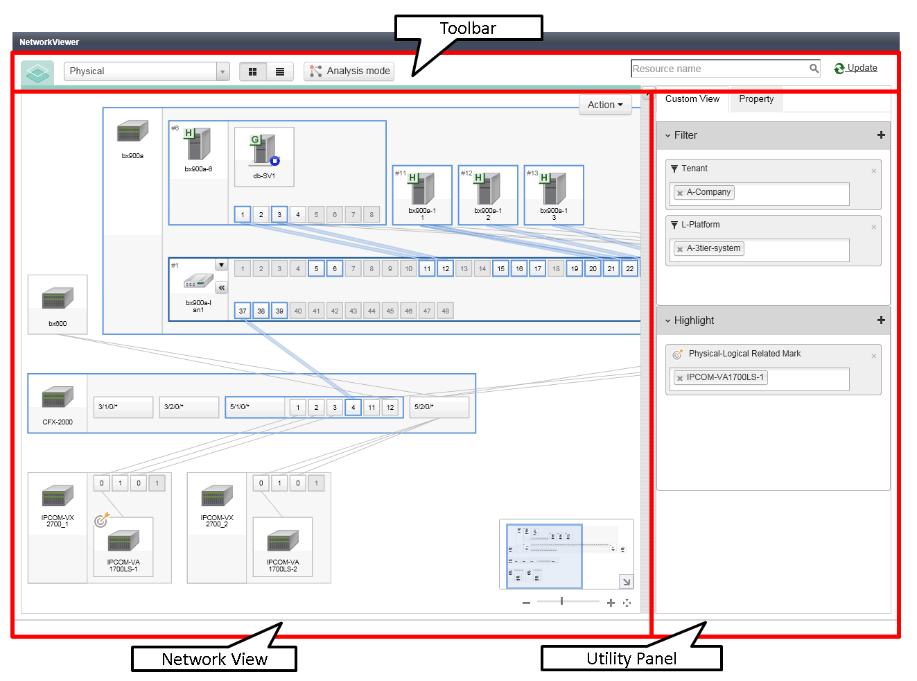
The NetworkViewer window consists of the tool bar, the network view, and the utility panel.
Figure 11.3 NetworkViewer Layout

The tool bar can be used to operate the network view.
Figure 11.4 Toolbar

This section explains the layout of the tool bar.
It is possible to switch between the physical view and the logical view.
Switches from the network view to the map view.
Switches from the network view to the list view.
For details on the list view, refer to "11.2.4 Network View (Physical List)" and "Network View (Logical List)11.2.5 Network View (Logical List)".
Starts the Analysis Mode window.
For details on the Analysis Mode window, refer to "11.2.8 Analysis Mode".
The area retrieved by the resource name.
Update NetworkViewer to show the latest status.
A view to display network configurations or resource lists.
The network view can be displayed in a map view or a list view.
Both the map format view and the list format view have two views: physical view and logical view.
Physical Map
Shows the statuses of registered resources and the network links between them.
For details, refer to "11.2.2 Network View (Physical Map)".
Logical Map
Shows the statuses of logical systems and the network links between them.
For details, refer to "11.2.3 Network View (Logical Map)".
Physical List
Shows the statuses of registered resources and parent resources in a list format.
For details, refer to "11.2.4 Network View (Physical List)".
Logical List
Shows the statuses and types of registered resources in a list format.
For details, refer to "11.2.5 Network View (Logical List)".
For the map view, the window display location can be scrolled by dragging and dropping.
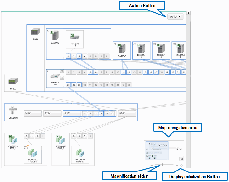
Figure 11.5 Network View

This section explains the Network view's layout.
Analysis Mode
This button performs operation of the Analysis Mode.
For details, refer to "11.2.8 Analysis Mode".
Export View Information
This button outputs the network view information as a CSV file.
Contact List
Displays the tenants to which the target resources belong and the contact information of the users who belong to those tenants.
All areas are displayed, including those that cannot be displayed by the network view.
The arrow button located in the lower right of the map navigation area enables opening and closing of the map navigation area.
By dropping and dragging the display frame in the map navigation area, the display location of the network view can be scrolled in coordination with the frame.
Maximizes or minimizes the network view.
The button that returns a window that has been moved to its default position.
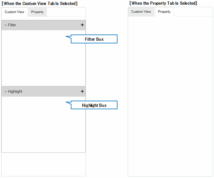
This view is the window to display the detailed information of the condition settings of network view display or resources.
Figure 11.6 Utility Panel

Use the custom view to filter and highlight resources.
For details, refer to "11.2.6 Utility Panel (Custom View)".
Resource details are displayed.
For details, refer to "11.2.7 Utility Panel (Property)".