This section describes the information that is displayed in a physical map of the network view.
Figure 11.11 Display Example of Network View (Physical List)
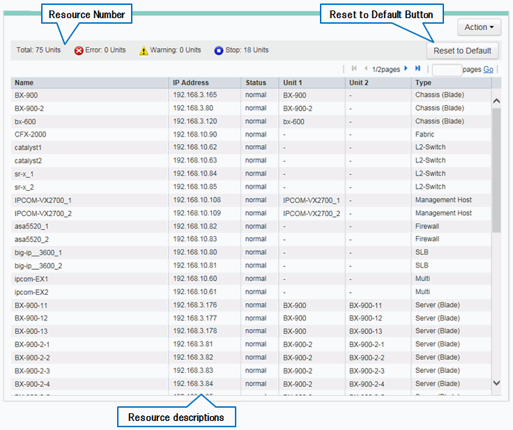
Displays the total number of resources displayed in a physical list as well as the number of each status (Error/Warning/Stop).
Displays the resource information in a table format.
An explanation of the items in the displayed table is given below.
Display Item | Description | Example |
|---|---|---|
Name (*1) | The name of the resource is displayed. | bx600-1 |
IP address | The admin LAN IP address of the resource is displayed. | 192.168.3.121 |
Device status | The status of the resource is displayed. | normal |
Unit 1 (*2) | The name of the unit in which the resource is stored is displayed. | bx600 |
Unit 2 (*2) | The name of the unit in which the resource is stored is displayed. | bx600-1 |
Category | One of the following is displayed as the resource type:
| Server (Blade) |
*1: When the resource status is "Error", "Warning", or "Stop", or when a "physical-logical relationship icon" is displayed for the resource, the corresponding status icon or the physical-logical relationship icon is displayed for that resource.
*2: For the resources that form a three-tier system (Unit1->Unit2->Resource), corresponding resource name is displayed in the "Name", "Unit1", and "Unit2" fields. For the resources that form a two-tier system (Unit1->Resource), corresponding name is displayed in the "Name" and "Unit1" fields and "-" is displayed in the "Unit2" field.
Example
When displaying a VM guest (in a three-tier system)
The VM guest name, chassis name, and the VM host name are displayed in the "Name", "Unit1", and "Unit2" fields, respectively.
When displaying IPCOM VA (in a two-tier system)
The name of the IPCOM VA, the name of the admin host (IPCOM VX), and "-" are displayed in the "Name", "Unit1", and "Unit2" fields, respectively.
Information
Clicking a column label in the physical list will sort the displayed resources in ascending or descending order.
However, the lines of the resources for which "-" is displayed under the clicked column label are always displayed in the lower part of the list.
Returns the displayed physical list to its initial state.