This section explains how to register resources to RMS using the "userApplication Configuration Wizard" screen.
The resources include the following:
Resource type | Outline |
|---|---|
Cmdline resources | Use this type to set a user-created script file or command as a resource. The resource is required to start or stop the ISV application or application in line with the userApplication state transition, and in the same way, to cause the state transition with the application stop. |
Fsystem resources | Mounts a file system at userApplication startup. |
Gds resources | Sets up a disk class in userApplication. The disk class is defined in Global Disk Services. |
Gls resources | Sets up a takeover IP address in userApplication. The Ipaddress is defined in Global Link Services (network redundancy). |
Takeover network resources | Sets up a takeover network in userApplication. The two types of takeover addresses are takeover IP address and takeover node name. |
Procedure resources | Sets up a state transition procedure in userApplication. |
Process monitoring resources | Sets up a user-created program to be monitored by the process monitoring function in userApplication. |
Line switching resources | Sets up a line switching unit in userApplication. |
ISV resources | Sets up an ISV (Independent Software Vendor) application in userApplication. |
Note
CUI (hvw) cannot display or operate any configuration that was created by using resources other than those listed above.
Note
Resource name
When you create a resource, first select a resource type and then enter a resource name. The resource name must be a string of 18 or fewer characters consisting of alphanumeric characters and "_" (underscore), starting with an uppercase alphabetic character. For this name, do not use the same name ("config") as the Configuration name or the same name ("Cmdline" and "Fsystem" etc.) as resource type name.
Example: Cmdline0
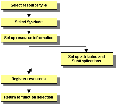
The flow of resource creation is shown below.
Figure 6.5 Resource creation flow
Note
When specifying an association (priority setting) between resources of the same type, create the resource starting from the one with the higher priority.
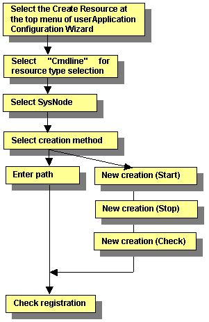
This section describes the procedure for creating Cmdline resources.
Figure 6.6 Flow of Cmdline resource creation
Creating resources
At the top menu of the "userApplication Configuration Wizard," select Create Resource.
Figure 6.7 Top menu of the userApplication Configuration Wizard
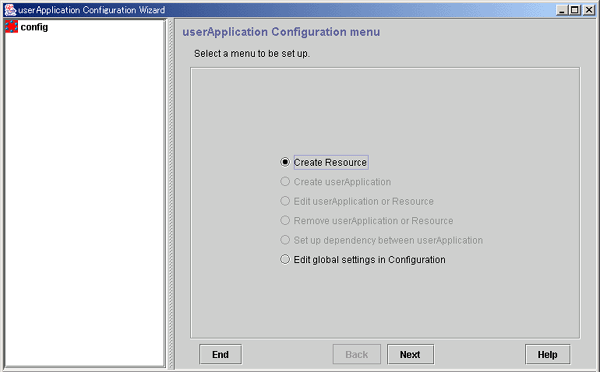
Click Next to go to the "Create Resource" screen.
Selecting the resource type
Select the type of resource that you want to create.
Figure 6.8 Create Resource
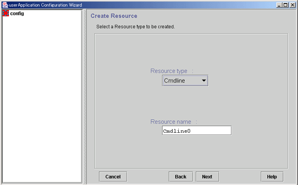
Select the type of resource to be created from the types described in the table below.
Cmdline (Cmdline resources)
Fsystem (Fsystem resources)
Gds (Gds resources)
Gls (Gls resources)
Ipaddress (Takeover network resources)
Procedure (Procedure resources)
Process (Process monitoring resources)
SH_SWLine (Line switching resources)
Oracle, Nwcl, Nwsv, Nwst (ISV resources)
When you create a resource, first select a resource type and then enter a resource name. The resource name must be a string of 18 or fewer characters consisting of alphanumeric characters and "_" (underscore), starting with an uppercase alphabetic character. For this name, do not use the same name ("config") as the Configuration name.
Click Next to go to the "Select SysNode" screen.
Selecting the SysNode
Select the SysNode in which the resource is to exist. SysNode refers to the CIP node name used by RMS.
Figure 6.9 Select SysNode
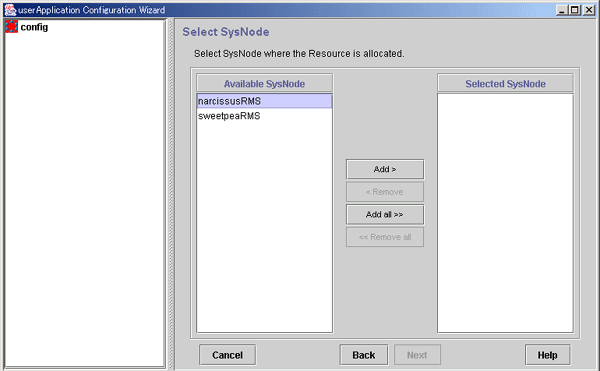
Of the nodes in a cluster system, only the names accessible through Web-Based Admin View are displayed.
The SysNode name in which the resource is to exist is displayed. This information is used as filtering information for the interfaces used by each resource.
From the Available SysNode, select the SysNode, and then click Add. To add all the listed SysNodes, click Add all.
To delete a SysNode, select the SysNode to be deleted from Selected SysNodes, and then click Remove. To delete all listed SysNodes, click Remove all.
Click Next to go to the "Set up each resource" page.
Selecting the Cmdline creation method
Cmdline resources are general-purpose resources. By defining three scripts for starting, stopping, and monitoring the user application (program) to be monitored, you can create a resource that matches the purpose.
The scripts correspond to the following processes in RMS
Select a method of configuring the script files and commands as the resource.
Figure 6.10 Set up command
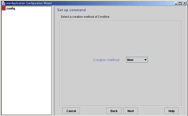
Select the creation method from the following:
New
You can create a new script file.
Path Input
You can specify the existing script or command.
Click Next.
After completing the setup, click Next. This will lead you to the following operation according to the selected item:
New: Creating new script files
Path input: Creating scripts by path input
Note
When you create a script, you must carefully create a script end value, a timeout value, and environmental variable. For details, see "Notes on script creation" in "6.6 Setting Up Online/Offline Scripts."
For details on the script sample, see "Sample scripts" in "6.6 Setting Up Online/Offline Scripts."
If you specify New for Creation method of Cmdline, the Start script creation screen appears.
The Cmdline contents can be input directly into the editing area. The text copy, cut, and paste operations are enabled only in the editing area.
Figure 6.11 Start script creation
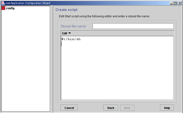
Specify the file name to be saved.
Note
The following characters cannot be used in the file path and the arguments.
= \ ~ % @ &
If you need to use those characters, create the script specified with usable names and arguments, and then execute the script that starts, stops, and monitors the resource.
Even though processing is cancelled or the screen is closed during Cmdline creation, the script files are still stored in the "/opt/FJSVwvucw/scripts/start" directory. Therefore the scripts can be reused when the Cmdline resources are re-created.
The way in which scripts are stored in the following directories differs depending on the type of the script:
Start script
/opt/FJSVwvucw/scripts/start
Stop script
/opt/FJSVwvucw/scripts/stop
Check script
/opt/FJSVwvucw/scripts/check
Note
When specifying arguments, separate the arguments with "blank" characters. Since the scripts that can be created in this screen are Bourne shell by default, the following string is displayed at the beginning of the editing area:
#!/bin/sh
You can edit scripts from the simplified menu. The editing operation is described below:
Item | Operation |
|---|---|
Move cursor | You can move the cursor to any position by placing the mouse pointer at the target position and single-clicking the mouse pointer or by operating the arrow keys on the keyboard in the top, bottom, left, or right directions. |
Insert text | You can input characters at the cursor position. |
Delete text | To delete 1 character Press the [Delete] key to delete the character at the cursor position. Press the [Backspace] key to delete the character positioned directly before the cursor position. To delete a string with one or more characters, use the following keys: [Delete] key [Backspace] key Edit -> Delete from the menu bar |
Cut text | Select a string with one or more characters in the editing area and go to Edit -> Cut. |
Copy text | Select a string with one or more characters in the editing area and go to Edit -> Copy. |
Paste text | Position the cursor at the position where the character string that was previously cut or copied within the editing area is to be pasted, and then select Edit -> Paste. |
Note
These script files are not removed even when processing is cancelled during Cmdline creation, or the Cmdline resource or GUI package (FJSVwvucw) is removed. If you want to remove the files, you need to remove the "/opt/FJSVwvcuw/scripts/start" directory. For example, execute the "rm(1)" command to remove one script file as follows:
# rm /opt/FJSVwvucw/scripts/start/XXXXXXXX
To remove the directory, specify "/opt/FJSVwvucw/scripts/start" or "/opt/FJSVwvucw."
Note that, when you delete a Stop script or Check script, replace the "start" portion in the above directory with "stop" or "check."
Click Next to go to "Stop script creation."
Create a Stop script by using the same procedure as that for the Start script.
Figure 6.12 Stop script creation
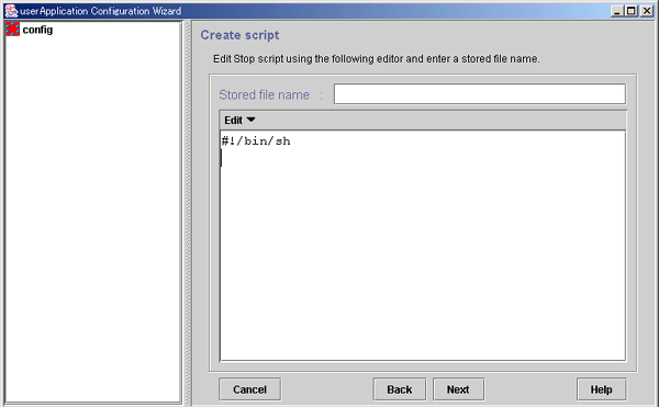
Click Next to go to "Check script creation."
Note
You can omit setup of this script file. Just click Next.
Create a Check script by using the same procedure as that for the Start script.
Figure 6.13 Check script creation
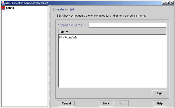
You can set script attributes from a dialog box. See "Setting up Cmdline flags," for details.
Note
If "NULLDETECTOR" was set to "Yes" at the "Set Cmdline Flag" screen, a Check script does not need to be configured. In this case, the Check script is not configured as resource information because the Check script is not started from RMS.
Creating scripts by path input
If a script already exists, you can enter a path to select the script.
Note
The following characters cannot be used in the file path and the arguments.
= \ ~ % @ &
If you need to use those characters, create the script specified with usable names and arguments, and then execute the script that starts, stops, and monitors the resource.
Figure 6.14 Cmdline setup
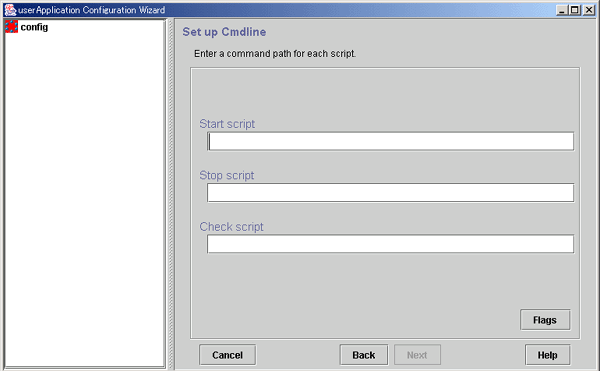
Enter the path of the Start script. If you are specifying arguments, separate the arguments with "blanks."
The Start script is always a required script. The script must be entered with a full path name.
Enter the path of the Stop script. If you are specifying arguments, separate the arguments with "blanks."
The Stop script is not required information. The script must be entered with a full path name.
Enter the path of the Check script. If you are specifying arguments, separate the arguments with "blanks." The script must be entered with a full path name.
Although the Check script is always a required script, it does not have to be specified if NULLDETECTOR was set to "Yes" in the "Set Cmdline Flag" screen. Even if the script is setup, the information is deleted during resource registration because the Check script is not started from RMS.
Set the script attributes. For information, see "Setting up Cmdline flags," which is described later.
The method of a controlling script defined to a Cmdline resource can be adjusted by changing the flag values.
The following default value is for Cmdline resource. Other resources have a default value individually.
Figure 6.15 Set up Cmdline flags
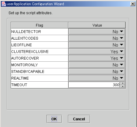
After completing the setup, click OK to return to the "Set up Cmdline" screen.
Flag | Outline |
|---|---|
NULLDETECTOR | It synchronizes with the Online/Offline processing of userApplication, and executing the Online/Offline script on the Cmdline resource. It is not monitored after the Online/Offline script on the Cmdline resource processing succeeded. |
ALLEXITCODES | If the flag is set to "No", the exit code of the Check script will be interpreted as follows: 0: Online If the flag is set to "Yes", the exit code of the Check script will be interpreted as follows: 0: Online The default value is "No." |
LIEOFFLINE | If this flag is set to "Yes," the resource is notified as being Offline if a Stop script is not specified. If a Stop script is specified, the failure of the script triggers fault processing. |
CLUSTEREXCLUSIVE | If this flag is set to "Yes", the resource becomes Online only on one node in a cluster system. If the resource becomes Online on two or more nodes at the same time because of a script problem, the state of userApplication to which this resource belongs becomes Inconsistent. |
AUTORECOVER | If this flag is set to "Yes," RMS tries to recover the resource if it becomes faulted. In this way, RMS tries to prevent the userApplication from being switched to another host |
MONITORONLY | This flag controls whether the "faulted" condition in the resource makes the userApplication Faulted. If this flag is set to yes, the resource becomes Faulted, but this does not make the userApplication Faulted. |
STANDBYCAPABLE | If this flag is set to "Yes," RMS sets the StandbyCapable attribute to 1 for this resource. For detailed information regarding this attribute, see "11 Appendix -Attributes" in "PRIMECLUSTER Reliant Monitor Services (RMS) with Wizard Tools Configuration and Administration Guide." |
REALTIME | If the flag is set to "No", the Check script will be started in the TS class (time-sharing scheduling) . |
TIMEOUT | This flag sets the timeout interval (seconds) for program start and stop processing. |
Check Cmdline registration information
You can check a list of the scripts that has been set up previously. You can also configure resource attributes by selecting the Attributes tab and switching the screen.
For information on the resource attributes, see "6.7.5 Attributes."
Figure 6.16 Confirmation of registration information
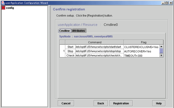
The attributes that are displayed in the "Flag" column are only those Resource attributes for which a value has been set. For example, if No is set for the AUTORECOVER attribute, then it means that AUTORECOVER attribute has not been set, and it is not displayed in the Flag column.
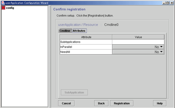
Associate the other Cmdline resources or process monitoring resources with the Cmdline resource that has been created above. See "Resource association."
After checking the registration information, click Registration.
Use this function to configure a startup sequence among resources of the same type.
By assigning startup priorities to resources, you can clarify the order in which the resources are to be switched to Online or Offline.
In Online processing, resources that have a high startup priority are switched to Online before resources that have a low startup priority.
Conversely in Offline processing, resources that have a low startup priority are switched to Offline before resources that have a high startup priority.
If a startup priority is not assigned or if resources have the same priority, the sequence is undefined.
Figure 6.17 Associate resources
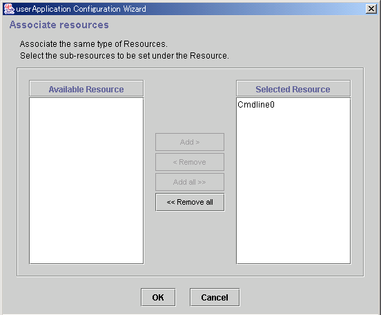
Available resource is referred to as the resource of the same type that can be associated, and satisfies the following conditions.
The resource is of the same type as the resource that was called.
The resource is not being used by another cluster application.
Note: Cmdline and process monitoring resources are considered the same type of resources.
Resources to be set under the current resource being created.
From Available Resource select the resource to be configured under the current resource, and then click Add. To add all listed resources, click Add all. To delete a resource from under the current resource, select the resource to be deleted from the Selected Resource, and then click Remove. To delete all listed resources, click Remove all.
After completing the setup, click OK, and return to the "Confirm Registration Information" screen.
Example
In the configuration shown below, the startup priority has been set to resources of the same type.
To build this configuration, build the resources according to the procedure shown below.
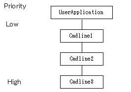
Create Cmdline3.
Create Cmdline2, and set Cmdline3 as subApplication.
Create Cmdline1, and set Cmdline2 as subApplication.
Create userApplication, and set Cmdline1 as subApplication.
The procedure for building the following configuration is shown below.
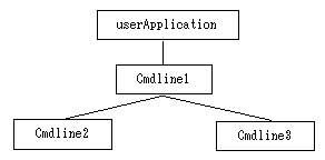
Create Cmdline3.
Create Cmdline2.
Create Cmdline1, and set Cmdline2 and Cmdline3 as subApplication.
Create userApplication, and set Cmdline1 as subApplication.
In the configuration shown below, the other resources were not set as subApplication during the creation of resource.

Set up an Fsystem resource if you want to mount a file system when userApplication is started.
To control multiple mount points in parent-child relationships, create the file system as one Fsystem resource.
You need to work on the following prerequisites to create an Fsystem resource.
Mount points are used to mount UFS and other local file systems.
The file system can be shared as an NFS file system in the network. The file system can also be set up so that it is not shared.
When a file system is shared in the network, the NFS Lock Failover function becomes enabled.
Notes on using the file lock facility
If you use an NFS server function, set it so that the Lock information for NFS is succeeded.
If a transfer of the Lock information for NFS is not possible, you can get multiple Lock information for the same file. Therefore, the application that uses fcnlt(2) and lockf(3C) cannot execute the exclusive control. And it becomes the factor to cause file destruction.
But the following attention is necessary on using this function. Execute the next attention whether an application uses a lock unidentified.
On the node operation with NFS servers, do not use the NFS client function. Do not implement NFS mount.
A file system in which NFS is shared with the operation of NFS servers must be used only from the NFS client. Do not use a file directly from an application on a node on which NFS servers are operating.
When failover occurs, the following processing is performed. The access from the client is reserved until the NFS lock recovery processing is completed though the state of the resource becomes Online when the start of statd and lockd is completed.
Stopping the statd(1M) and lockd(1M) daemon
Starting the statd(1M) and lockd(1M) daemon
NFS lock recovery processing
When a mountpoint is shared using NFS, only one Fsystem resource including the mountpoint can be set to a single userApplication. In addition, the Fsystem resource must include the mountpoint where the NFS Lock Failover was set.
userApplication0
    Fsystem0
        mountpoint0  (NFS share, NFS Lock Failover)
        mountpoint1  (NFS share)
        mountpoint2  (NFS share)
        mountpoint3  (NFS share)
Note
It is not configured as about the following.
Setting multiple Fsystem resources including the NFS lock Failover setting to a single userApplication
userApplication0
    Fsystem0
        mountpoint0  (NFS share, NFS Lock Failover)
        mountpoint1  (NFS share)
    Fsystem1
        mountpoint2  (NFS share, NFS Lock Failover)
        mountpoint3  (NFS share)
Setting multiple Fsystem resources including the NFS share setting to a single userApplication
userApplication0
    Fsystem0
        mountpoint0  (NFS share, NFS Lock Failover)
        mountpoint1  (NFS share)
    Fsystem1
        mountpoint2  (NFS share)
        mountpoint3  (NFS share)
Note that NFS Lock may not be temporarily obtained from NFS clients for the NFS file system controlled by userApplication1 may occur in the case of a failover on userApplication0 with the configuration below.
Setting was multiple userApplication/Fsystem
userApplication0
    Fsystem0
        mountpoint0  (NFS share, NFS Lock Failover)
        mountpoint1  (NFS share)
userApplication1
    Fsystem1
        mountpoint2  (NFS share, NFS Lock Failover)
        mountpoint3  (NFS share)
Notes on using NFS
Protocols
NFS can use TCP and UDP protocols. After using TCP for failover and failback in sequence, recovery sometimes takes longer than with UDP. Therefore, please use the UDP protocol in PRIMECLUSTER.
Creating 31 or more mount points in Fsystem resources
The minimum Timeout value of the Fsystem resource is determined by the formula " No. of mount points in Fsystem resources x 6 seconds".
The default timeout is 180 seconds. If you set 31 or more mount points in Fsystem resources, it is necessary to change Timeout to the proper value based on "No. of mount points in Fsystem resources x 6 seconds" by selecting the Attributes tab in the screen shown in "Checking Fsystem registration information."
This section describes operations that must be performed before the file system is set up with the GUI. Although not mentioned in the procedure, editor commands such as those featured by vi(1) are generally used in file editing.
Editing the /etc/vfstab.pcl file
Register the ZFS Storage Pool to /etc/vfstab.pcl
Perform the following procedure up to "2 Registering the legacy file system to /etc/vfstab.pcl" with all nodes which configure the cluster.
Add the entry to /etc/vfstab.pcl for the ZFS storage pool created above. Set the following information for the respective items.
bdev : "#RMS#<ZFS storage pool name>"
cdev : "<ZFS storage pool name>"
mount point : "<mountpoint>"
fstype : "zfs"
runlevel, auto mount, flags : "-"
If the mountpoint is not set to the ZFS storage pool (default), set the name of the mountpoint as the ZFS storage pool name with the prefix "/".
Below is an example of registering two entries, the one of which is the ZFS storage pool named app1 and the mountpoint is set to /mnt, the other is the ZFS storage pool named app2 and the mountpoint is not set.
# bdev cdev mountpoint fstype runlevel auto mount flags
#RMS#app1 app1 /mnt zfs - - -
#RMS#app2 app2 /app2 zfs - - -
Register the legacy file system to /etc/vfstab.pcl
If one has created a legacy file system, in addition to the ZFS storage pool, add entries for each of the legacy file systems. Set the following information for the respective items.
bdev : "#RMS#<file system name>"
cdev : "<file system name>"
mount point : "<mountpoint>"
fstype : "zfs"
runlevel, auto mount, flags : "-"
Below is an example of settings for when creating two legacy file system app/mpl and app/mp2 to the ZFS storage pool app and with their respective mountpoints being /appdata1 and /appdata2.
# bdev cdev mountpoint fstype runlevel auto mount flags
#RMS#app app /app zfs - - -
#RMS#app/mp1 app/mp1 /appdata1 zfs - - -
#RMS#app/mp2 app/mp2 /appdata2 zfs - - -
Define the mount point in the "/etc/vfstab.pcl" file on all nodes where userApplication is configured to use Fsystem.
#RMS#/dev/sfdsk/class0001/dsk/volume0001 /dev/sfdsk/class0001/rdsk/volume0001 /disk1 ufs - no -
#RMS#/dev/sfdsk/class0001/dsk/volume0002 /dev/sfdsk/class0001/rdsk/volume0002 /disk2 ufs - no -
Note
Lines must begin with "#RMS#".
You cannot set different volumes on the same mount point.
Editing autofs
The file system and mount point to register into the Fsystem resources cannot be used in autofs.
When the device of a file system and the directory of a mount point added in "Editing the /etc/vfstab.pcl file" are used in autofs, delete the corresponding entry from the /etc/auto_master.
Preparations for sharing a file system in a network (NFS)
See
For settings when sharing the ZFS non-legacy file systems in NFS, see "6.4.1.2 Setup Procedure."
1) Create Ipaddress or Gls resources
Since a takeover network is necessary when an NFS service is used as a cluster application, create an Ipaddress or a Gls resource.
For details on the setup procedure, see "6.7.1.5 Creating Takeover Network Resources" and "6.7.1.4 Creating Gls Resources."
Note
Set this resource to the same userApplication as the Fsystem resource.
2) Carry out preparations for enabling NFS Lock Failover
Select the "Edit global settings in Configuration" command from the menu, and specify the settings for enabling NFS Lock Failover.
For details on the setup procedure, see "6.7.4 Editing global settings in Configuration."
Note that you must register one or more UFS or ZFS legacy file systems with Fsystem resources as the location of directories. NFS file lock information to be registered in "6.7.4 Editing global settings in Configuration" is stored there.
Moreover, you need to change the version of NFS to use and the settings of SMF for enabling NFS Lock Failover. Perform the following procedure corresponding to the environment you are using.
When you use NFS Lock Failover in Solaris 10, perform "Prerequisites for NFS Lock Failover (for Solaris 10)."
When you use NFS Lock Failover in Solaris 11, perform "Prerequisites for NFS Lock Failover (for Solaris 11)."
Perform the following procedure for all cluster nodes to use NFS Lock Failover.
1) Log in to the corresponding cluster node as system administrator.
2) Change the setting file of NFs /etc/default/nfs as below.
# Sets the maximum version of the NFS protocol that will be registered
# and offered by the server. The default is 4.
#NFS_SERVER_VERSMAX=4
NFS_SERVER_VERSMAX=3
       .
       .
# Sets the maximum version of the NFS protocol that will be used by
# the NFS client. Can be overridden by the "vers=" NFS mount option.
# If "vers=" is not specified for an NFS mount, this is the version
# that will be attempted first. The default is 4.
#NFS_CLIENT_VERSMAX=4
NFS_CLIENT_VERSMAX=3
3) Execute the command below for each node to configure a cluster.
# /usr/bin/script -a /var/opt/reliant/log/smfchg_cnf.log <Return>
# /usr/sbin/svcadm -v disable -s network/nfs/client <Return>
# /usr/sbin/svcadm -v disable -s network/nfs/server <Return>
# /usr/sbin/svcadm -v disable -s network/nfs/nlockmgr <Return>
# /usr/sbin/svcadm -v disable -s network/nfs/status <Return>
# /usr/sbin/svccfg -v delete -f network/nfs/status <Return>
# /usr/sbin/svccfg -v delete -f network/nfs/nlockmgr <Return>
# /usr/sbin/svccfg -v delete -f network/nfs/server <Return>
# /usr/sbin/svccfg -v delete -f network/nfs/client <Return>
# /usr/sbin/svccfg -v import /var/svc/manifest/network/nfs/status.xml <Return>
# /usr/sbin/svccfg -v import /var/svc/manifest/network/nfs/nlockmgr.xml <Return>
# /usr/sbin/svccfg -v import /var/svc/manifest/network/nfs/server.xml <Return>
# /usr/sbin/svccfg -v import /var/svc/manifest/network/nfs/client.xml <Return>
# /usr/sbin/svccfg -v -s network/nfs/status setprop network/restart_on=astring: none <Return>
# /usr/sbin/svccfg -v -s network/nfs/status setprop rpcbind/restart_on=astring: none <Return>
# /usr/sbin/svccfg -v -s network/nfs/status setprop filesystem-local/restart_on=astring: none <Return>
# /usr/sbin/svccfg -v -s network/nfs/status addpg startd framework <Return>
# /usr/sbin/svccfg -v -s network/nfs/status addpropvalue startd/duration astring: transient <Return>
# /usr/sbin/svccfg -v -s network/nfs/nlockmgr setprop network/restart_on=astring: none <Return>
# /usr/sbin/svccfg -v -s network/nfs/nlockmgr setprop rpcbind/restart_on=astring: none <Return>
# /usr/sbin/svccfg -v -s network/nfs/nlockmgr setprop status/restart_on=astring: none <Return>
# /usr/sbin/svccfg -v -s network/nfs/nlockmgr setprop filesystem-minimal/restart_on=astring: none <Return>
# /usr/sbin/svccfg -v -s network/nfs/nlockmgr addpg startd framework <Return>
# /usr/sbin/svccfg -v -s network/nfs/nlockmgr addpropvalue startd/duration astring: transient <Return>
# /usr/sbin/svccfg -v -s network/nfs/server setprop nlockmgr/restart_on=astring: none <Return>
# /usr/sbin/svccfg -v -s network/nfs/client setprop nlockmgr/restart_on=astring: none <Return>
# /usr/sbin/svccfg -s svc:/network/nfs/status setprop stop/exec = astring: ":true" <Return>
# /usr/sbin/svccfg -s svc:/network/nfs/nlockmgr setprop stop/exec = astring: ":true"  <Return>
# /usr/sbin/svcadm -v refresh network/nfs/status <Return>
# /usr/sbin/svcadm -v restart network/nfs/status <Return>
# /usr/sbin/svcadm -v enable -s network/nfs/status <Return>
# /usr/sbin/svcadm -v refresh network/nfs/nlockmgr <Return>
# /usr/sbin/svcadm -v enable -s network/nfs/nlockmgr <Return>
# /usr/sbin/svcadm -v refresh network/nfs/server <Return>
# /usr/sbin/svcadm -v enable -s network/nfs/server <Return>
# /usr/sbin/svcadm -v refresh network/nfs/client <Return>
# /usr/sbin/svcadm -v enable -s network/nfs/client <Return>
4) Confirm that four SMF services below are online.
# /usr/bin/svcs | grep nfs <Return>
online          0:51:53 svc:/network/nfs/client:default
online          0:51:54 svc:/network/nfs/status:default
online          0:51:54 svc:/network/nfs/nlockmgr:default
online          0:51:55 svc:/network/nfs/server:default
5) Exit the script command.
# exit <Return>Execute the following procedures in all the cluster nodes which use the NFS Lock Failover.
1) Login to the target cluster node using a system administrator.
2) Execute the following commands for each node which configures the clusters.
# /usr/bin/script -a /var/opt/reliant/log/smfchg_cnf.log <Return>
# /usr/sbin/svcadm -v disable -s network/nfs/client <Return>
# /usr/sbin/svcadm -v disable -s network/nfs/server <Return>
# /usr/sbin/svcadm -v disable -s network/nfs/nlockmgr <Return>
# /usr/sbin/svcadm -v disable -s network/nfs/status <Return>
# /usr/sbin/svccfg -v delete -f network/nfs/status <Return>
# /usr/sbin/svccfg -v delete -f network/nfs/nlockmgr <Return>
# /usr/sbin/svccfg -v delete -f network/nfs/server <Return>
# /usr/sbin/svccfg -v delete -f network/nfs/client <Return>
3) Start svccfg, and update the settings for SMF.
# svccfg <Return>
  svc:> select network/nfs/status <Return>
  svc:/network/nfs/status> delcust <Return>
  svc:/network/nfs/status> select network/nfs/nlockmgr <Return>
  svc:/network/nfs/nlockmgr> delcust <Return>
  svc:/network/nfs/nlockmgr> select network/nfs/server <Return>
  svc:/network/nfs/server> delcust <Return>
  svc:/network/nfs/server> select network/nfs/client <Return>
  svc:/network/nfs/client> delcust <Return>
  svc:/network/nfs/client> quit <Return>
4) Execute the following commands for the each node which configure the clusters.
# /usr/sbin/svccfg -v import /lib/svc/manifest/network/nfs/status.xml <Return>
# /usr/sbin/svccfg -v import /lib/svc/manifest/network/nfs/nlockmgr.xml <Return>
# /usr/sbin/svccfg -v import /lib/svc/manifest/network/nfs/server.xml <Return>
# /usr/sbin/svccfg -v import /lib/svc/manifest/network/nfs/client.xml <Return>
5) Change the NFS settings as shown below.
# /usr/sbin/sharectl set -p server_versmax=3 nfs <Return>
# /usr/sbin/sharectl set -p client_versmax=3 nfs <Return>
6) Execute the following commands for the each node which configures the clusters in sequence.
# /usr/sbin/svccfg -v -s network/nfs/status setprop network/restart_on=astring: none <Return>
# /usr/sbin/svccfg -v -s network/nfs/status setprop rpcbind/restart_on=astring: none <Return>
# /usr/sbin/svccfg -v -s network/nfs/status setprop filesystem-local/restart_on=astring: none <Return>
# /usr/sbin/svccfg -v -s network/nfs/status addpg startd framework <Return>
# /usr/sbin/svccfg -v -s network/nfs/status addpropvalue startd/duration astring: transient <Return>
# /usr/sbin/svccfg -v -s network/nfs/nlockmgr setprop network/restart_on=astring: none <Return>
# /usr/sbin/svccfg -v -s network/nfs/nlockmgr setprop rpcbind/restart_on=astring: none <Return>
# /usr/sbin/svccfg -v -s network/nfs/nlockmgr setprop status/restart_on=astring: none <Return>
# /usr/sbin/svccfg -v -s network/nfs/nlockmgr setprop filesystem-minimal/restart_on=astring: none <Return>
# /usr/sbin/svccfg -v -s network/nfs/nlockmgr addpg startd framework <Return>
# /usr/sbin/svccfg -v -s network/nfs/nlockmgr addpropvalue startd/duration astring: transient <Return>
# /usr/sbin/svccfg -v -s network/nfs/server setprop nlockmgr/restart_on=astring: none <Return>
# /usr/sbin/svccfg -v -s network/nfs/client setprop nlockmgr/restart_on=astring: none <Return>
# /usr/sbin/svccfg -s svc:/network/nfs/status setprop stop/exec = astring: ":true" <Return>
# /usr/sbin/svccfg -s svc:/network/nfs/nlockmgr setprop stop/exec = astring: ":true" <Return>
# /usr/sbin/svcadm -v refresh network/nfs/status <Return>
# /usr/sbin/svcadm -v restart network/nfs/status <Return>
# /usr/sbin/svcadm -v enable -s network/nfs/status <Return>
# /usr/sbin/svcadm -v refresh network/nfs/nlockmgr <Return>
# /usr/sbin/svcadm -v enable -s network/nfs/nlockmgr <Return>
# /usr/sbin/svcadm -v refresh network/nfs/server <Return>
# /usr/sbin/svcadm -v enable -s network/nfs/server <Return>
# /usr/sbin/svcadm -v refresh network/nfs/client <Return>
# /usr/sbin/svcadm -v enable -s network/nfs/client <Return>
7) Confirm the following four SMF services are online.
# /usr/bin/svcs | grep nfs <Return>
online          0:51:53 svc:/network/nfs/client:default
online          0:51:54 svc:/network/nfs/status:default
online          0:51:54 svc:/network/nfs/nlockmgr:default
online          0:51:55 svc:/network/nfs/server:default
8) Exit the script command.
# exit <Return>3) Set up the NFS entry of PRIMECLUSTER
When all file systems to be shared in NFS are ZFS non-legacy file systems, make a directory with UFS or a ZFS legacy file system separately, and then add the entry of the file system. The NFS file lock information registered in "6.7.4 Editing global settings in Configuration" is stored there.
When all file systems to be shared in NFS are UFS or ZFS legacy file systems, add entries of the file systems.
In both cases, edit the /etc/dfs/dfstab.pcl file.add. Add the entries of the file systems to be shared in NFS on all nodes that make up userApplication.
#RMS# share -F nfs /disk1
#RMS# share -F nfs /disk2
Note
Be sure to start each entry with "#RMS#."
The definition of each entry follows when the file system is shared in NFS manually by the share (1M) command.
For UFS or ZFS legacy file systems, a file system can be shared in NFS by the mount point defined in /etc/vfstab.pcl.
For ZFS non-legacy file systems, the sharing process of NFS or monitoring the NFS shared status on with Fsystem is not performed because ZFS performs the sharing process of NFS.
If another file system is used
The disk must be formatted and the file system must be created beforehand. For information on formatting and file system commands, see the "Solaris X Reference Manual Collection." If you plan to use ZFS as the file system, see "6.4.1 If using ZFS" when you build the file system.
This section describes how to create Fsystem resources.
Figure 6.18 Flow of Fsystem resource creation
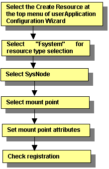
For information on the above operations up to "Select SysNode," see "6.7.1.1 Creating Cmdline Resourcesmdline Resources." This section describes the operations starting from "Select mount point."
Selecting mount points
Figure 6.19 Select mount point
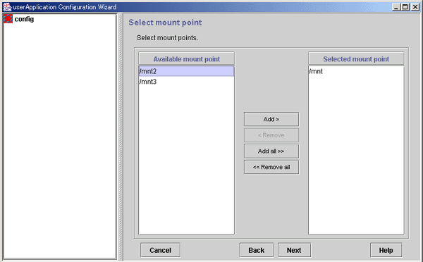
Names of mount points where the file system can be mounted.
The mount points that were configured for "/etc/vfstab.pcl" (described earlier) are displayed.
Names of mount points to be used for file system mounting.
From Available mount point, select the mount point at which the file system is to be mounted, and then click Add. To add all listed mount points, click Add all. To delete a mount point on which the file system is not going to be mounted, select the mount point to be deleted from Selected mount point, and then click Remove. To delete all listed mount points, click Remove all.
After completing the setup, click Next to go to "Setting mount point attributes."
Note
Setup of the ZFS storage pool's resource is performed with the create Fsystem resource screen. Since the ZFS storage pool's highest level mount point that was defined to the /etc/vfstab.pcl file is displayed on the mount point selection screen, please select that and embed the resource in the userApplication.
Even if there is the ZFS dataset used as a ufs file system or legacy file system, the setup is performed with the create Fsystem resource screen.
Select the mount point with the mount point selection screen and embed the resource in the userApplication.
If the ZFS dataset used as a ZFS legacy file system exists on the ZFS storage pool of a shared disk, set a mountpoint corresponding to the ZFS storage pool's highest level mountpoint and the dataset of the legacy file system to a single Fsystem resource.
Setting mount point attributes
Set attributes for the mount points.
Figure 6.20 Select attribute
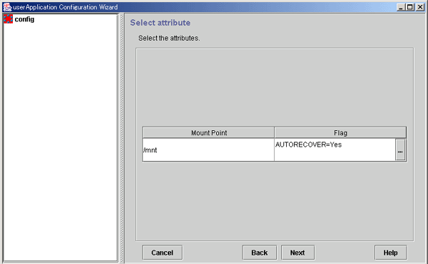
The mount name is displayed.
The attributes that are set for the individual mount points are displayed.
Press this button to set attributes for controlling mount point management. When this button is clicked, the Set Mount Button Attributes screen shown below is displayed.
After completing the setup, click Next to go to "Fsystem Registration Information Confirmation."
Attribute setup for mount points
Configure the attributes for controlling the mount points.
Figure 6.21 Attribute setup for mount points
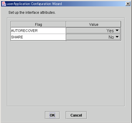
After completing the setup, click OK to go to the "Select Attribute" screen.
Flag | Outline |
|---|---|
AUTORECOVER | If this flag is set to "Yes" and the specified file system is unmounted, RMS automatically attempts to remount the specified file system when it is unmounted. If this attempt fails, Fault processing is initiated. |
SHARE | If this flag is set to Yes, a mounted directory is shared (NFS). In such a case, make a specific entry to "/etc/dfs/dfstab.pcl". See "Preparations for sharing a file system in a network (NFS)" in "6.7.1.2.1 Prerequisites." |
NFSLOCKFAILOVER | If this flag is set to "Yes," Lock information for NFS Lock Failover is stored for this mount point. To use NFS Lock Failover, you must set this flag to "Yes" for one of the mount points. If you set this attribute to "Yes," you must also set SHARE to "Yes" at the same time. The default value is "No." |
Checking Fsystem registration information
Check the Fsystem registration information. You can also select the Attributes tab, and set resource attributes by switching the screen.
For information on the resource attributes, see "6.7.5 Attributes."
Figure 6.22 Confirmation of registration information
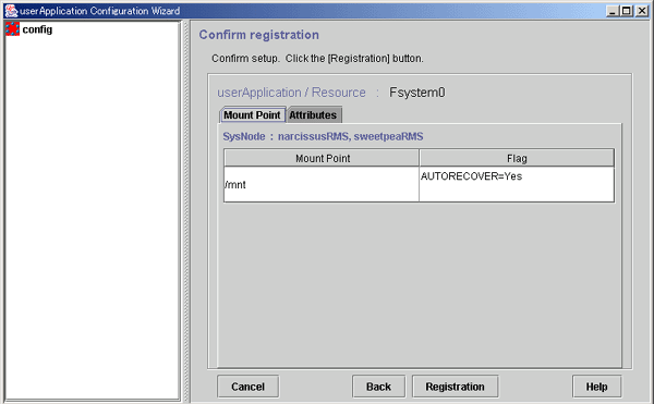
The attributes that are displayed in the "Flag" column are only those Resource attributes for which a value has been set. For example, if "No" is set for an attribute that takes a "Yes" or "No" setting, such as AUTORECOVER, that attribute is not displayed in the "Flag" column.
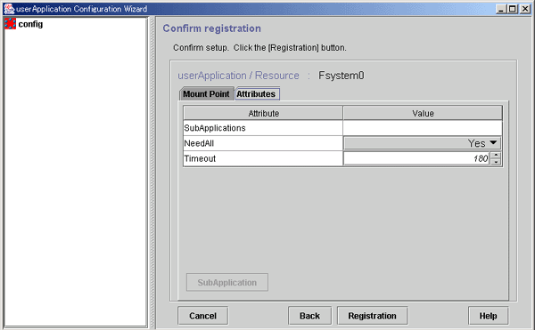
This button is used for specifying other resources that the current resource depends on. For an Fsystem resource, this button is disabled.
For multiple directories in parent-child relationships, configure the directories in one resource.
Check the registration contents, and then click Registration.
Set up resources for the disk classes that are defined in Global Disk Services (GDS).
The disk classes must be created before this screen is used.
Note
If a disk class is registered to a Gds resource when equivalent volume copy is being executed, the equivalent copy operation is canceled. Therefore, the data becomes invalid in some of the slices. However, recovery is not necessary because equivalent copy is executed automatically when the volume is started. If you want to recover the slice state before the volume is started, complete Gds resource setup and then start equivalent copy. For instructions on starting equivalent copy, see "5.3.6 Copying Operation" or "D.10 sdxcopy - Synchronization copying operation" in the "PRIMECLUSTER Global Disk Services Configuration and Administration Guide."
For instructions on creating disk classes, see "6.3.2.3 Setting Up Shared Disks."
Figure 6.23 Flow of Gds resource creation
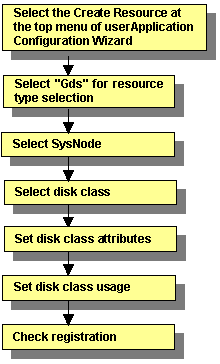
For information on the above operations up to "Select SysNode," see "6.7.1.1 Creating Cmdline Resources." This section describes the operations starting from "Select disk class."
Selecting the disk class
Figure 6.24 Select disk class
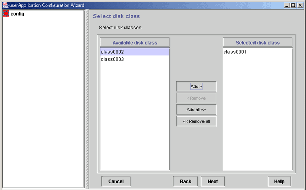
Names of disk classes that can be set.
The disk classes (shared disks) that are defined in GDS are displayed.
Names of disk classes to be set.
Select disk classes from Available disk class, and then click Add. To add all listed disk classes, click Add all. To delete a disk class to be set, select the disk class to be deleted from Selected disk class, and then click Remove. To delete all listed disk classes, click Remove all.
After completing the setup, click Next to go to the "Set Disk Class Attribute" screen.
Disk class attribute setup
Set the disk class attribute.
Figure 6.25 Set up disk class attribute
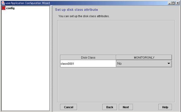
The disk classes (common disks) that were defined in GDS (described earlier) are displayed.
Flag | Outline |
|---|---|
MONITORONLY | This flag determines whether disk class failures are to be reported to the userApplication. If "Yes" is set and a disk class failure occurs, the disk class is switched to faulted state but the Gds resources remain online, and userApplication failover does not occur. Carry out the preliminary design, including the higher applications" before determining the disk classes for which this flag is to be set to "Yes." |
The MONITORONLY attribute must be set to "No" for at least one disk class.
This will prevent userApplication failover in the event of all disk class failures and RMS' notifying the upper applications of the failures.
After completing the setup, click Next to go to the "Set up disk class use" screen.
Setting the disk class use
Configure the use of the disk class.
Figure 6.26 Set up disk class use
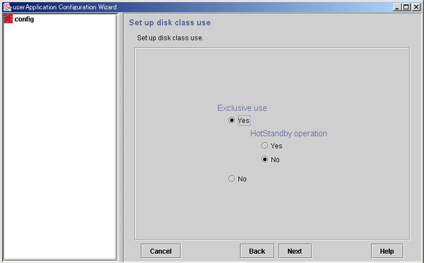
Select "Yes" or "No" for Exclusive use. If you select "Yes", also select "Yes" or "No" for HotStandby operation.
Specify the options according to the use of the shared disk.
After completing the setup, click Next to go to the "Confirm Registration Information" screen.
Use | Exclusive use | HotStandby operation |
|---|---|---|
Switched disk | Yes | No |
Shared disk for simultaneous access | Yes | Yes |
Simultaneous shared disk | No | - |
Shared disks have the following features for each use:
Switched disk
Only the OPERATING node can use the shared disk.
The non-OPERATING nodes cannot access the volume.
Shared disk for simultaneous access
All nodes can use the shared disk simultaneously.
Select this use if applications that require disk access from a node other than the OPERATING node are set inside the same userApplication.
The exclusive control for maintaining data integrity in the shared disk must be handled by the applications, and not by PRIMECLUSTER.
Simultaneous shared disk
Select this use if multiple userApplications share the disk classes. An example is when Oracle real application clusters are used.
The exclusive control for maintaining data integrity in the shared disk must be handled by the applications, and not by PRIMECLUSTER.
Note
During operation of a cluster application, try not to have applications or user processes that are not related to the cluster applications use the shared disks. If this occurs, the state transition might fail.
Do not create a home directory for user accounts on a switchover disk. The reasons are as follows:
The file system on the switching disk is mounted only on the OPERATING node of the cluster application.
PRIMECLUSTER forcibly terminates process that uses the file system on the switching disk by executing the "kill(1M)" command to unmount the file system in the event of cluster application failover.
If the file system cannot be unmounted properly because of a failure of forced termination of process, PRIMECLUSTER might forcibly stop the node to prevent the file system data on the shared disk from being destroyed by double mounting.
Checking registration information for Gds resources
Check the registration information for the Gds resources. You can also set resource attributes by selecting the Attributes tab and switching the screen.
For information on the resource attributes, see "6.7.5 Attributes."
Figure 6.27 Confirm registration
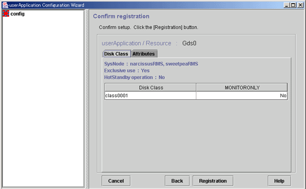
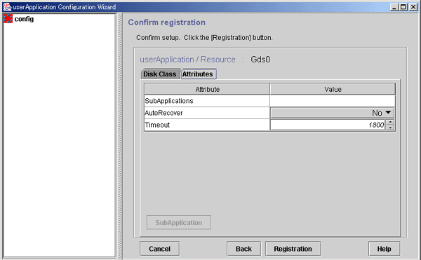
Use this button to associate a previously created Gds resource under the current Gds resource. This button can be selected only if there are resources of the same type that can be associated. For setting instructions, see "Resource association" in "6.7.1.1 Creating Cmdline Resources."
Check the registration information, and then click Registration.
Configure the takeover IP addresses that are defined by the redundant line control function of Global Link Services (GLS).
Note
For details on using the multipath function of Global Link Services (GLS), see "Chapter 7 Administration on a Cluster System" in "PRIMECLUSTER Global Link Services Configuration and Administration Guide: Multipath Function."
Figure 6.28 Flow of Gls (redundant line control function) resource creation
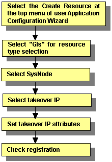
For information on the above operations up to "Select SysNode," see "6.7.1.1 Creating Cmdline Resourcesmdline Resources." This section describes the operations from "Select takeover IP."
Selecting the takeover IP address
Select the takeover IP address.
Figure 6.29 Takeover IP address selection
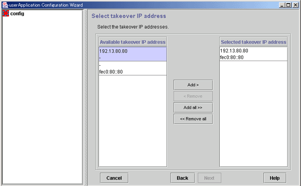
IP addresses that can be taken over.
Takeover IP addresses.
From Available takeover IP address, select takeover IP addresses, and then click Add. To add all listed takeover IP addresses, click Add all. To delete a takeover IP address, select the takeover IP address to be deleted from Selected takeover IP address, and then click Remove. To delete all listed takeover IP address, click Remove all.
After completing the setup, click Next to go to the "Set Takeover IP Address Attribute" screen.
Setting attributes of the takeover IP address
Set the attributes of the takeover IP address.
Figure 6.30 Attribute setup for the takeover IP address
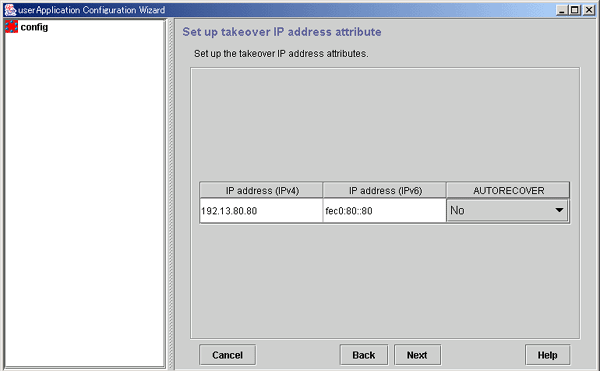
After completing the setup, click Next to go to "Checking Gls Resource Registration Information."
Flag | Outline |
|---|---|
AUTORECOVER | If the flag is set to "Yes," RMS attempts to restore the faulted resource for a given amount of time to prevent userApplication being switched to the other host. The default timeout is 60 seconds. You can change it by tuning the resource attribute Timeout. |
Checking registration information for Gls resources
Check the registration information for the Gls resources. You can also set resource attributes by selecting the Attributes tab and switching the screen.
For information on the resource attributes, see "6.7.5 Attributes."
Gls resource names are displayed as GlsX (X is a number, such as 0 or 1).
To register a Gls resource to a cluster application, select this resource name from Available Resources on the Select Resource screen.
For details, see "6.7.2 Creating Cluster Applications."
Figure 6.31 Confirmation of registration information
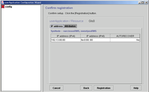
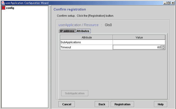
Use this button to associate a previously created Gls resource under the current Gls resource. This button can be selected only if there are resources of the same type that can be associated. For setting instructions, see "Resource association" in "6.7.1.1 Creating Cmdline Resources."
After checking the registration information, click Registration.
Normally to use a takeover network, use either "Gls" (Global Link Services) or "Ipaddress" as the resource type. If the availability of the takeover network is needed, use "Gls."
A takeover network must be set up if you are building a system like a client/server system that communicates with cluster services that operate in the cluster system.
Takeover networks allow communication to continue with the same network name from outside the cluster even if a cluster application that operates in the cluster system undergoes failover.
Takeover network types
The takeover network types are IP address takeover and node name takeover.
IP address takeover
When switchover takes place, the defined IP address is taken over to the OPERATING node.
This is the basic function of a takeover network.
Node name takeover
The node name* is also taken over to the OPERATING node.
Use this type if a program that operates as a cluster application in the cluster node recognizes node names.
* This is the same value as the host name that is obtained when uname -n is executed.
In a Solaris 11 environment, change the node name by using the svccfg(1M) command and so on.
Files that are edited automatically by the GUI
If the GUI is used to execute the setup, certain files are edited as shown below.
The files differ according to the takeover network type.
# Start of lines added by FJSVwvucw - DO NOT DELETE OR CHANGE THIS LINE
# Mon Aug 05 21:01:43 JST 2002
<Specify information that is dependent on that particular file. For example, for /etc/inet/hosts, the information becomes as follows:>
192.168.246.100 Ipaddress01
# End of lines added by FJSVwvucw - DO NOT DELETE OR CHANGE THIS LINE
IP address takeover
/etc/inet/hosts
/usr/opt/reliant/etc/hvipalias
Node name takeover
/etc/inet/hosts
/usr/opt/reliant/etc/hvipalias
/etc/nodename
Note
In node name takeover, the same node name is set to both the OPERATING node and the STANDBY node.
All cluster nodes must have at least one network interface card so the card can be used.
Although a PRIMECLUSTER "takeover network" and the "IP address takeover" function of GLS can be set up in the same cluster system, do not use them on the same interface. If the two are used on the same interface, connection using takeover IP addresses will be disenabled.
For example, if you select hme1 as the interface to be used when you set up the PRIMECLUSTER "takeover network," do not set hme1 in the GLS environment settings (do not specify hme1 in the -t option of the "hanetconfig create" command).
You cannot assign takeover networks to network interfaces used in the shared or exclusive IP zones, which are delegated to non-global zones.
This section describes how to create takeover network resources.
Figure 6.32 Flow of takeover network resource creation
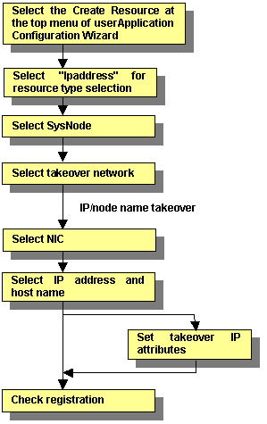
For information on the above operations up to "Select SysNode," see "6.7.1.1 Creating Cmdline Resourcesmdline Resources." This section describes the operations starting from "Select takeover network."
Selecting a takeover network
Select the takeover network type.
Figure 6.33 Network type selection
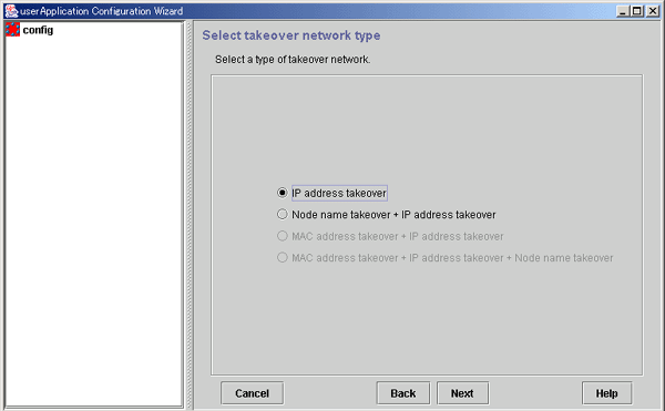
Select this item to enable IP address takeover.
Select this item to enable node name takeover and IP address takeover.
If node name takeover has already been set, you are not allowed to set twice.
"MAC address takeover + IP address takeover" and "MAC address takeover + node name takeover + IP address takeover" cannot be selected.
You can configure a network interface for each SysNode. The takeover network settings are enabled for one network interface:
Multiple IP address takeover settings are enabled for each network interface.
Only one node name takeover setting is enabled in a cluster system.
After completing the setup, click Next to go to the "Select Interface" screen.
Note
To activate a network interface card (NIC) when the system is started, you must do the following in advance:
For Solaris 10
Create the "/etc/hostname.network_interface_name" file, and then define the IP address (or the host name) in the file.
For Solaris 11
Use the ipadm(1M) command for setting. Specify a different value from other IP addresses.
Node name takeover changes the uname of the system. To set node name takeover for userApplication, you need to restart all nodes configuring userApplication.
If a node name takeover resource has been deleted, check whether /etc/nodename has been properly changed in all nodes, and then restart all nodes. If /etc/nodename has not been properly changed, change the node name by executing the "setuname(1M)" command, and then restart the nodes.
Also check whether /etc/nodename is set properly when system conversion or software upgrade is implemented. If /etc/nodename is not set properly, change the node name by executing the "setuname(1M)" command, and then restart the nodes.
Selecting an interface
Select a network interface card (NIC).
The NIC cards registered to Cluster Resource Manager are displayed.
Figure 6.34 Select interface
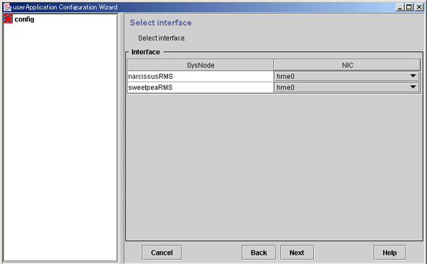
Select the network interface to be used in each SysNode.
After completing the setup, click Next to go to the "Select IP address and host name" screen.
Selecting or creating an IP address or host name
Select or create the takeover IP address or host name.
Figure 6.35 Selection screen for IPv4 address and host name
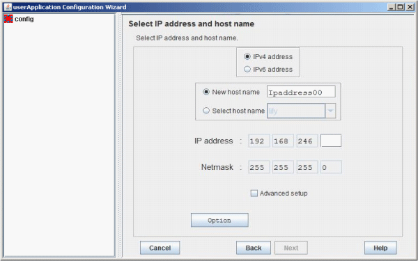
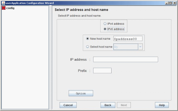
Figure 6.36 Selection screen for IPv6 address and host name
Select "IPv4 address" when creating a takeover IP address of an IPv4 address.
Select "IPv6 address" when creating a takeover IP address of an IPv6 address.
You can set a new takeover IP address and a takeover node name. The setup information is added to the "/etc/inet/hosts" or "/usr/opt/reliant/etc/hvipalias" file on all nodes configuring the cluster system.
Specify a character string of up to 14 characters that begins with an alphabet letter and consists of only alphanumeric characters.
You can select the IP address or node name from information that has been set. If IP addresses or node names were previously configured to /etc/inet/hosts and /usr/opt/reliant/etc/hvipalias, select the IP address or node name from those settings.
Enter the takeover IP address.
When you select "IPv4 address," enter 0 to 255 numbers in the address input area.
When you select "IPv6 address," enter an IPv6 address.
Enter the net mask value.
Enter 0 to 255 numbers in the address input area.
Set the prefix length.
Enter 0 to 128 numbers in the prefix length input area.
Set up a masked net mask or change an IP address.
Press this button to configure attributes for the takeover IP address. For more information, see "Setting up Takeover IP Address Attributes" below.
Note
If /usr/opt/reliant/etc/hvipalias and /etc/inet/hosts files have been modified to accommodate the entries for the takeover IP address and node name takeover in advance (as described in the Prerequisites section), message 0840 appears when the Next button is clicked. This message confirms whether the existing values are to be used without modification. To use the values, select Yes.
If you select No, the existing settings in the file are deleted and the GUI re-creates the information. In this case, takeover network information can be deleted automatically from /usr/opt/reliant/etc/hvipalias and /etc/inet/hosts when the Ipaddress resource is deleted.
IPv6 link local addresses are not available for IP addresses.
Setting up Takeover IP Address Attributes
Configure the interface attributes for the takeover IP address.
Figure 6.37 Attribute setup for takeover IP address
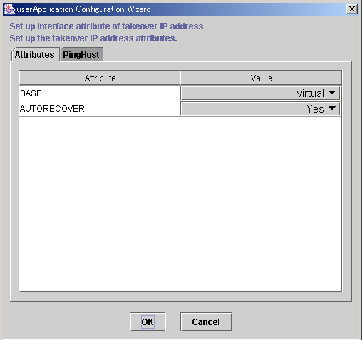
Flag | Outline |
|---|---|
BASE | If this flag is set to "base," the specified address is assigned to the physical interface. |
AUTORECOVER | If this flag is set to "Yes," RMS automatically attempts to create an interface if the specified address becomes disabled. A failure of this attempt might trigger Fault processing. |
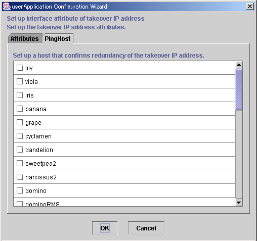
After the setup is completed, click OK to return to the "Select IP address and host name" screen.
The availability of the takeover IP address is verified by executing the "ping" command.
We recommend that you specify two or more hosts, which are not used for the cluster system, and are in the same network segment that does not use a hub or router. This prevents adverse effects from hub and router failures.
The host information to be used by PingHost must be in /etc/inet/hosts.
Checking registration information for the takeover network
Check the registration information for the takeover network. You can also set resource attributes by selecting the Attributes tab and switching the screen.
For information on the resource attributes, see "6.7.5 Attributes."
Figure 6.38 Confirm registration
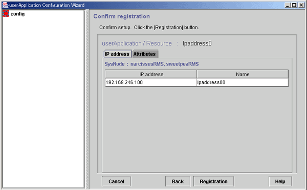
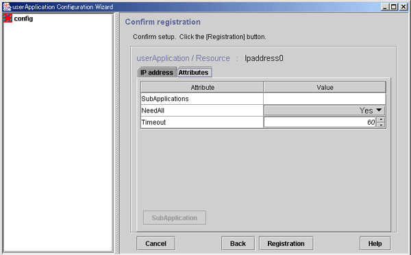
Select this button to associate a previously created takeover network under the current takeover network. This button can be selected only if there are resources of the same type that can be associated. For setting instructions, see "Resource association" in "6.7.1.1 Creating Cmdline Resources."
Check the registration information, and then click Registration.
A procedure resource must be created to migrate a SynfinityCluster product to PRIMECLUSTER. Procedure resources can be created only for those products described in "Part 7 PRIMECLUSTER Products."
To create a procedure resource, you must first create a state transition procedure and register the procedure to the resource database on all nodes in the cluster system.
Note
If a process is started without process monitoring from a state transition procedure, the hard- and software limits of the file descriptor (fd) for the process may be changed.
If the hard- and software limits of the file descriptor (fd) for the system are less than 1024, the hard- and software limits of the file descriptor (fd) for the process started from a state transition procedure will be 1024.
In the process started from a state transition procedure, if you need to set the value less than 1024 for the hard- and software limits of the file descriptor (fd), add a "ulimit" definition at the beginning of processing for the state transition procedure, and specify the hard- and software limits of the file descriptor (fd).
Example
For setting both hard- and software limits of the file descriptor (fd) to 256:
#!/bin/sh
ulimit -n 256
...
See
For details on how to register a state transition procedure, see "Appendix F Registering, Changing, and Deleting State Transition Procedure Resources for SynfinityCluster Compatibility."
Register the procedure resources that were registered to the cluster resource manager to RMS.
Figure 6.39 Flow of procedure resource creation
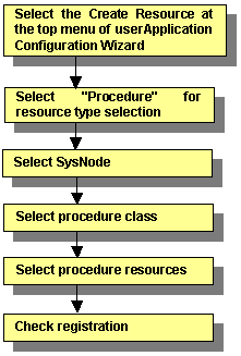
For information on the above operations up to "Select SysNode," see "6.7.1.1 Creating Cmdline Resourcesmdline Resources." This section describes the operations from Select procedure class.
Selecting the procedure class
Select the procedure class to be created.
Figure 6.40 Select procedure class
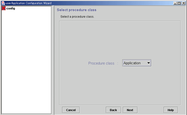
Select the procedure class. Only the resource classes of resources that have been registered to the cluster resource manager are displayed. For example, if only procedure resources of the Application class have been registered, only Application is displayed.
The class resource manager provides four standard procedure classes:
Application
This class is used to make general applications to be cluster-aware.
BasicApplication
It is a class used for DBMS.
SystemState2
It is used to make a part of OS functionality cluster-aware. This OS function should be started at "/etc/rc2.d" in a non-cluster single node. SystemState2 does not automatically start during OS startup. It is used to start a cluster application only on the OPERATING node.
SystemState3
It is used to make a part of OS functionality cluster-aware. This OS function should be started at "/etc/rc3.d" in a non-cluster single node. SystemState3 does not automatically start during OS startup. It is used to start a cluster application only on the OPERATING node.
Note
To create an application resource that is set in one cluster application on each node, the application resource name should be the same as the application type on each node.
After completing the setup, click Next to go to the "Select procedure resource" screen.
Selecting the procedure resource
Select the procedure resource to be created.
Figure 6.41 Select procedure resource
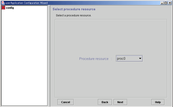
Select the procedure resource to be created from the displayed list. The procedure resource name consists of up to 32 characters.
After completing the setup, click Next to go to the "Confirm registration" screen.
Checking the registration information for the procedure resource
Check the registration information for the procedure resource. You can also set resource attributes by selecting the Attributes tab and switching the screen.
For information on the resource attributes, see "6.7.5 Attributes."
Figure 6.42 Confirm registration
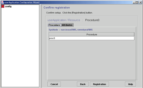
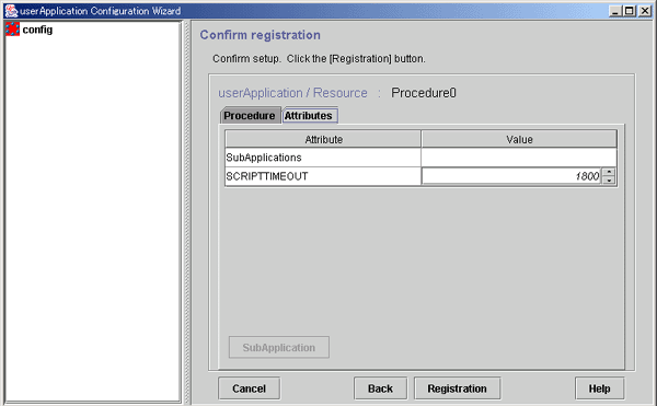
This button associates the other procedure resources to the procedure resource that has been created above. For more information, see "Associate resources," which is described later.
Check the registration information, and then click Registration.
Resource Association
Use resource association to assign a startup order to resources of the same type.
Figure 6.43 Associate resources
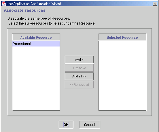
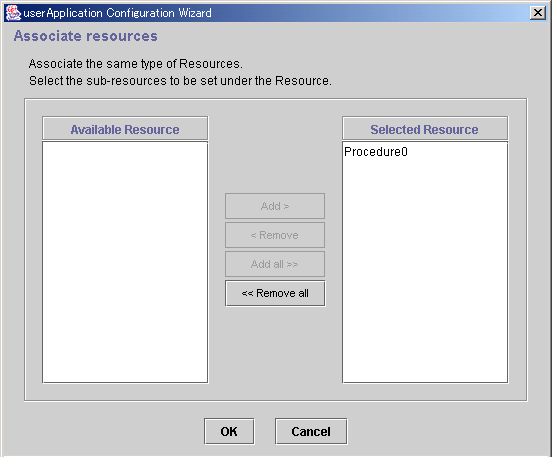
Available resource is referred to as the resource of the same type that can be associated, and satisfies the following conditions.
The resource is of the same type as the resource that was called.
The resource is not being used by another cluster application.
Resources to be set under the current resource being created.
From Available Resource, select the resources to be configured under the current resource, and then click Add. To add all listed resources, click Add all. To remove a resource, select the resource to be removed from Selected Resource, and then click Remove. To delete all listed resources, click Remove all.
After completing the setup, select OK to return to the "Confirm registration" screen.
This section describes how to set up process monitoring resources.
Before describing the setup method, this section also outlines the process monitoring function and prerequisites for specific uses.
Overview of the process monitoring function
The process monitoring function monitors the live state of processes. The main features are as follows:
Changes in the live status of a process can be monitored.
(This setup is quite easy, so the user does not need to prepare commands for monitoring the live status of a process.)
Notifies RMS of the live state of any process immediately, and this provides high-speed switchover.
If any process terminates abnormally because of an unexpected error, that process is automatically restarted.
A relationship diagram of the process monitoring function and RMS is shown below. The process monitoring function consists of three components: the "clmonproc" command, the Process Monitoring Daemon (prmd), and the Detector (hvdet_prmd).
"clmonproc" command
The "clmonproc" command is executed from the Online or Offline script. The command requests prmd to start a specified process and to stop live monitoring.
prmd daemon
prmd is a daemon process that starts a process and stops live monitoring according to requests received from the "clmonproc" command. If the live state of a process being monitored changes, prmd notifies hvdet prmd immediately.
hvdet_prmd daemon
After receiving change information on the live state of a process from prmd, the "hvdet prmd" process notifies the RMS Base Monitor (BM) of the changes.

Benefits of using the process monitoring function
Described below are the benefits of using the process monitoring function.
Since prmd monitors whether there are any processes to be monitored, the user does not need to create a check command for each process to be monitored. The check command is used to determine whether the process to be monitored exists. Therefore with little work, the user can easily monitor the existence of processes.
If the process monitoring function is not used, abnormal termination of a monitored process is detected by using a Cmdline resource to execute the "aforementioned check" command periodically. This delays detection of abnormal termination of a monitored process by execution time interval of the check command. However, if the process monitoring function is used, prmd uses signal processing to detect abnormal termination in monitored processes. This process monitoring function allows abnormal process termination to be detected at high speed compared to when check commands are executed periodically.
If any process terminates abnormally because of an unexpected error, the process monitoring function restarts that process automatically.
To shorten the time required to detect abnormal termination of a monitored process without using the process monitoring function, you must shorten the execution time interval of the check command. However, since this leads to frequent generation and execution of the check command, many CPU resources may be used up. Generally a command like the "ps" command is used as the check command. However, when a command that uses relatively more CPU resources, like the "ps" command, is used, the CPU resource consumption may become even more pronounced.
When the process monitoring function is used, prmd uses a signal process to monitor abnormal termination of the monitored process. A process that uses many CPU resources, such as one that issues a check command periodically, is not executed.
With the method that uses Cmdline resources, the number of check commands increases in proportion to the number of RMS objects because a check command is executed for each RMS object that is defined by the process to be monitored. Therefore if many check commands are executed periodically, many CPU resources may be used.
When the process monitoring function is used, it is always just one prmd that monitors the live stage of the process. Therefore, prmd does not use many CPU resources in proportion to the increase in the number of processes to be monitored.
Normally, you do not need to work on this prerequisite for using the process monitoring function. This is required only when you want to use the processing monitoring function for the specific purpose described below.
The identification number of the detector (the state notification module for notifying RMS) used by the process monitoring function is the same as the identification number to be used by other functions.
Note
The GUI uses "0" (default value) as the detector identification number of the process monitoring function. If a detector identification number other than "0" is already used, use that value.
This setup is required only for changing the detector identification number from the default value "0."
In this setup, the setting of the detector identification number must not exceed the allowed value "127."
Configure the same detector identification number on all cluster nodes.
Stop RMS and all running cluster applications on all nodes before changing the identification number.
Example
In the example described below, the detector identification number of the process monitoring function is changed from the initial value "0" to "2."
If the process monitoring function is being used with the initial value "0," the setting
<detector_name_of_process_monitoring_function>.g<identification_number> will exist. Remove that setting.
# cd /usr/opt/reliant/bin
# ls -l  hvdet_prmd.g0
lrwxrwxrwx   1 root     other         31 Dec 20 12:21 hvdet_prmd.g0 -> /usr/opt/reliant/bin/hvdet_prmd
# rm hvdet_prmd.g0
Execute the "clmonsetdet" command as shown below. For the command argument, specify "2," which is the new detector identification number.
# /etc/opt/FJSVcluster/bin/clmonsetdet 2
Check whether the settings were set correctly.
# ls -l  hvdet_prmd.g2
lrwxrwxrwx   1 root     other         31 Dec 27 12:21 hvdet_prmd.g2 -> /usr/opt/reliant/bin/hvdet_prmd
#
This section explains how to create process monitoring resources.
Figure 6.44 Flow of process monitoring resource creation
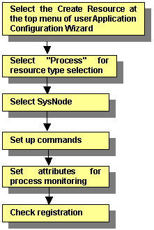
For information on the above operation up to "Select SysNode," see "6.7.1.1 Creating Cmdline Resourcesmdline Resources." This section describes the operations from "Set startup path."
Inputting the process startup command
Enter the startup path of the process to be monitored.
Figure 6.45 Set up command
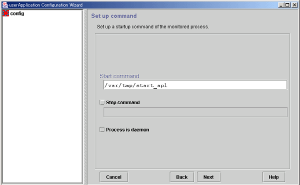
Enter the program name for starting the process to be monitored during online processing using a full path. If spaces are included in the full pathname, the pathname must be enclosed in double quotation marks (").
For example, enter the command line as follows:
"/var/tmp 1/start_apl"
The process monitoring function cannot monitor the following processes. It is necessary to specify a start command for each process monitoring resource.
Programs that exit out of own after initiating the other programs in the background.
Example: Shell script that exits out of own after starting three programs of "prog0", "prog1", and "prog2".
    #!/bin/sh

    prog0 &
    prog1 &
    prog2 &

    exit 0
Be aware that the process monitoring function cannot monitor child process that is generated with the start command.
Enter the method for stopping the monitored process during Offline processing.
If there is a command for stopping the monitored process, set the checkbox to ON, and enter the command line using a full path. If spaces are included in the command line, the command line must be enclosed in double quotation marks (").
For example, enter the command line as follows:
"/var/tmp 1/stop_apl"
If the stop command is omitted, the software exit signal (hereafter referred as SIGTERM) is sent from the process monitoring facility to stop the monitored process. Some processes might not be stopped by SIGTERM. In that case, Offline processing will fail.
Specify this item if the monitored process is to be operated as a daemon.
A daemon refers to a process that executes the following types of processes at startup:
Execution in the background
Promotion to process group leader
The former refers to child process generation when the fork system call is issued and termination of the parent process when the exit system call is issued. The latter refers to promotion to process group leader when the setpgrp system call is issued.
Note
The following characters cannot be used in the file name or the arguments: back slash ("\"), tilde ("~"), percent sign ("%"), ampersand ("&"), and at sign ("@").
Single quotation marks ("''") and tabs cannot be entered.
If a stop command is entered, a script for executing that command is created automatically. The script is stored in the following directory:
/opt/FJSVwvucw/scripts/process_stop
Setting attributes for the process
Enter attributes for the process to be monitored
Figure 6.46 Set up process monitoring attribute
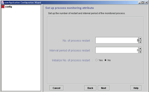
Specify the number of times the monitored process is to be restarted between 0 and 99 (default is 3). If 0 is specified and the monitored process stops, the process will become Faulted.
This is the interval from when the process monitoring facility determines that the process has stopped until the facility executes restart. The specification range is 0 to 3600 seconds (default: 3 seconds).
Specify whether or not the counter that has the specified No. of process restart value in the process monitoring facility as its maximum value is to be initialized periodically. If you select Yes, the counter is initialized every "No. of process restart value x 60 seconds." If you select No, the counter is not initialized periodically.
Checking the registration information of the process monitoring resource
Check the registration information for the process monitoring resource. You can also configure resource attributes by selecting the Attributes tab and switching the screen.
For information on the resource attributes, see "6.7.5 Attributes."
Figure 6.47 Confirm registration
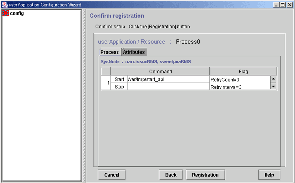
RetryCount indicates the number of times the process is to be restarted.
RetryInterval indicates the interval before starting the process.
Initialize=Yes indicates that the retry count of the process is to be initialized periodically. If No was specified for Initialize No. of process restart in the "Set up process monitoring attribute" screen, this attribute is not displayed.
Daemon=Yes indicates that the process is to be started as a daemon. If Process is daemon was not checked at the command setup screen, this attribute is not displayed.
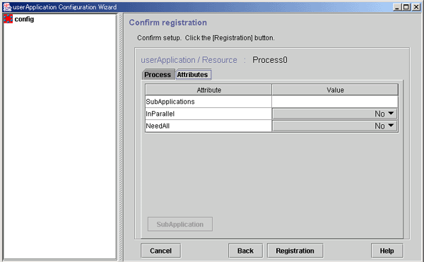
This button associates the other processing monitoring resources to the Cmdline or process monitoring resource that has been created above. This button can be selected only if there are resources that can be associated. For setting instructions, see "Resource association" in "6.7.1.1 Creating Cmdline Resourcesmdline Resources."
After checking the registration information, click Registration.
This section describes how to create line switching unit resources.
You should complete on the prerequisites before creating a line switching unit resource.
Line switching unit resources are available only in an Oracle Solaris 10 environment.
You must always perform the setup described below before using a line switching unit resource.
Resource registration
To use a line switching unit, you must first register a switching line resource (SH_SWLine class) to the resource database.
This section describes the procedure for registering a switching line resource to the resource database.
Registration procedure flow
Check the resource name of the line switching unit.
Register the switching line resource.
Check the registration information.
Registration procedure
Confirmation of the resource name of the line switching unit resource
Check the resource names of the line switching units that are registered to the resource database by using the "clgettree(1)" command.
# clgettree
Cluster 1 cluster
     Domain 2 CLUSTER
          Shared 7 SHD_CLUSTER
                  SHD_DISK 21 SHD_Disk21 UNKNOWN
                          DISK 22 c5t0d0 ON node1
                          DISK 27 c4t0d0 ON node2
                  SH_SWU 18 SWU2002 UNKNOWN
          Node 3 node1 ON
                  Ethernet 29 hme0 ON
                  DISK 19 c0t0d0 UNKNOWN
                  DISK 22 c5t0d0 ON
          Node 5 node2 ON
                  Ethernet 30 hme0 ON
                  DISK 25 c0t0d0 UNKNOWN
                  DISK 27 c4t0d0 ON
In this example, the line indicating "SH_SWU" shows the resource name is "SWU2002". If you cannot confirm the resource name, see "5.1.3.2 Automatic Configure" and register the line switching units to the resource database.
See
For details on the information that is output by executing the "clgettree(1)" command, see "Explanation of resources related to line switching units."
For details on the "clgettree(1)" command, see the manual page.
Registration of switching line resources
Execute the "claddswursc(1M)" command to add the switching line resources to the resource database.
# claddswursc -k sh_swl_1 -s SWU2002 -0 node1 -1 node2 -m 0x3
In this example, the line switching unit called "SWU2002," which was checked in step 2, is used to register the switching line resource called "sh_swl_1."
Port 0 of the switching unit is connected to "node1," and port 1 to "node2."
Since the two switching units LSU01 and LSU00 are to be used, the mask value is set to 0x3.
See
For details on the "claddswursc(1M)" command, see the manual page.
Confirmation of registration information
Execute the "clgettree(1)" command to check that the switching unit resources of the line switching unit have been registered to the resource database.
Example) Resources of the "SWLine" class are the switching unit resources of the line switching unit.
The resources of the "SH_SWLine" class show a sharing relationship of the switching units for the line switching unit.
      # /etc/opt/FJSVcluster/bin/clgettree
      Cluster 1 cluster
           Domain 2 CLUSTER
                Shared 7 SHD_CLUSTER
                        SHD_DISK 21 SHD_Disk21 UNKNOWN
                                DISK 22 c5t0d0 ON node1
                                DISK 27 c4t0d0 ON node2
                        SH_SWU 18 SWU2002 UNKNOWN
                                SH_SWLine 19 sh_swl_1 UNKNOWN
                                      SWLine 35 sh_swl_1P0 UNKNOWN node1
                                      SWLine 36 sh_swl_1P1 UNKNOWN node2
                Node 3 node1 ON
                        Ethernet 29 hme0 ON
                        DISK 19 c0t0d0 UNKNOWN
                        DISK 22 c5t0d0 ON
                        SWLine 35 sh_swl_1P0 UNKNOWN
                Node 5 node2 ON
                        Ethernet 30 hme0 ON
                        DISK 25 c0t0d0 UNKNOWN
                        DISK 27 c4t0d0 ON
                        SWLine 36 sh_swl_1P1 UNKNOWN
Explanation of resources related to line switching units
This section explains the information that is output by the "clgettree" command.
[Output example]
Cluster 1 cluster
     Domain 2 CLUSTER
          Shared 7 SHD_CLUSTER
               SHD_DISK 21 SHD_Disk21 UNKNOWN
                       DISK 22 c5t0d0 ON node1
                       DISK 27 c4t0d0 ON node2
               SH_SWU 18 SWU2002 UNKNOWN                          .....(a)
                       SH_SWLine 19 sh_swl_1 UNKNOWN              .....(b)
                             SWLine 35 sh_swl_1P0 UNKNOWN node1   .....(c)
                             SWLine 36 sh_swl_1P1 UNKNOWN node2   .....(d)
          Node 3 node1 ON
                  Ethernet 29 hme0 ON
                  DISK 19 c0t0d0 UNKNOWN
                  DISK 22 c5t0d0 ON
                  SWLine 35 sh_swl_1P0 UNKNOWN
          Node 5 node2 ON
                  Ethernet 30 hme0 ON
                  DISK 25 c0t0d0 UNKNOWN
                  DISK 27 c4t0d0 ON
                  SWLine 36 sh_swl_1P1 UNKNOWN
[Explanation]
In the example shown in the above figure, "SWU2002" is the resource name of the resource representing the line switching unit.
This resource is displayed when PRIMECLUSTER recognizes the line switching unit when automatic resource registration is executed.
In the example shown in the above figure, "sh_swl_1" is the resource name of the switching line shared resource (switching line name).
This resource is displayed when the switching line resources of the line switching unit are registered to the resource database with the "claddswursc" command.
As shown in the example of the above figure, this resource belongs to the "SH_SWLine" class.
These lines represent switching line resources of the line switching unit.
In the example shown in the above figure, "sh_swl_1P0" and "sh_swl_1P1" are resource names for switching line resources.
These resources are displayed when the switching line resources of the line switching unit are registered to the resource database with the "claddswursc" command.
As shown in the example of the above figure, these resources belong to the "SWLine" class.
This section describes the procedure for setting up a line switching unit resource.
Figure 6.48 Flow of creating a line switching unit resource
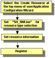
For information on the above operations up to "Selecting SH_SWLine for resource type selection," see "6.7.1.1 Creating Cmdline Resourcesmdline Resources." This section describes the operations from "Set resource information."
Note
The displayed Help information when you click the Help button includes the information for CUI only.
Setting resource information
Display the top screen.
Select SH_SWLine for the resource type selection. The following screen is displayed:
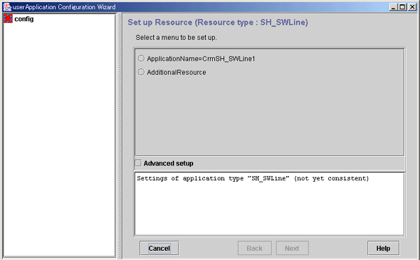
To terminate the selection process, click the Cancel button.
Check the name of the line switching unit resource.
name in ApplicationName=name is the name of the line switching unit resource to be created.
If the name is correct, go to step 5.
To change the name, go to step 3.
Select ApplicationName=name and click the Next button.
The screen for changing the resource name is displayed.
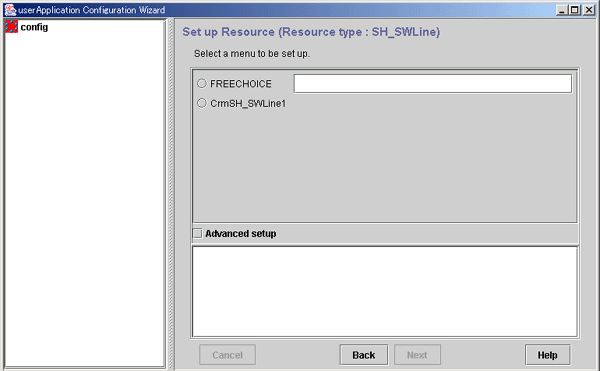
Click FREECHOICE and enter the resource name. After entering the name, click the Next button.
An updated top screen containing the entered information is displayed. Go to step 2 to check the information.
Select the Advanced setup checkbox.
A new menu will be added to the screen.
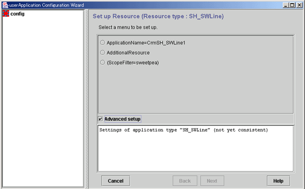
Check the nodes to which the line switching unit is connected.
node-names in ScopeFilter=node-name shows the CF node names, which are separated with colons (":").
If all nodes to which the line switching unit is connected are displayed, go to step 9.
If there is an error, go to step 7.
Information
Of the switching line resources (SH_SWLine class) that are registered to the resource database, those resources that are common to these nodes can be added to the line switching unit resource according to the procedure described later.
Select ScopeFilter=node-names" and click Next button.
The screen for entering the nodes to which the line switching unit is connected is displayed.
Click FREECHOICE and enter the names of the CF nodes to which the line switching unit is connected. Separate the names with colons (":"). After entering the CF node names, click the Next button.
An updated top screen containing the entered information is displayed. Go to step 5 and check the information.
Select AdditionalResource and then click the Next button.
The screen for selecting switching line resources that are registered to the resource database is displayed.
In the example shown in this screen, you can select the switching line resource called sh_swl_1. If no other data is displayed besides FREECHOICE, the following causes can be considered:
There is an error in the nodes that were checked in step 5.
No switching line resource is registered to the resource database.
For the first case, return to step 5 and check the nodes. To return to step 5, click the Back button.
For the second case, see "6.7.1.8.1 Prerequisites" and register a switching line resource to the resource database. To do this, click the Back button, and then click the Cancel button in the displayed screen. This stops the setup process, and you can start again from the beginning.
Select switching line resource from the candidate list, and click Next.
The top menu to which the switching line resource was added is displayed.
The information is displayed as follows:
   cluster_resource[number]=rsc-name
         number     A number corresponding to the sequence in which the resource was added is assigned.
         rsc-name   The resource name that was added is displayed.
Note
The attribute must not be changed. If you add a switching line resource, the Attribute menu is added. If you use this menu to change any attribute of the switching line resource, RMS will not operate correctly.
Go to step 1 of "Registering the information."
Registering the information
Select SAVE+EXIT.
When you select SAVE+EXIT, the Next button changes to the Registration button.
Note
If there is information that can be registered, the SAVE+EXIT menu will be added to the top screen.
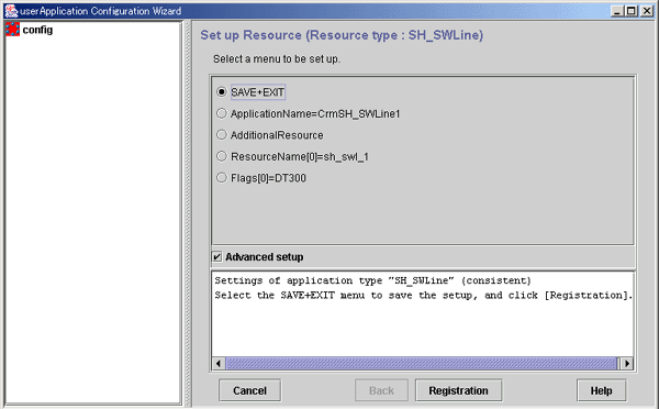
Click the Registration button.
A line switching unit resource will be created according to the specified information, and the "userApplication Configuration Wizard Menu" screen will be displayed.
This ends the procedure.
For information on ISV resource creation, refer to the manuals for the individual products.