This section describes the following operations and concepts required for the Storage Cluster function:
TFOV
TFOV is a volume for which failover is enabled.
Among TFOVs created on both the Primary Storage and the Secondary Storage, those TFOVs that have the same Host Logical Unit (HLU) number and capacity are volumes whose data is synchronized. In addition to data synchronization, the volume information on the Secondary Storage is changed as shown in "Table 9.1 Change in Volume Information on Pre- and Post-Data Synchronization Secondary Storage".
Volume Information to be Changed | Pre-Data Synchronization | Post-Data Synchronization |
|---|---|---|
UID | UID unique to volume on the Secondary Storage. | UID of volume on the Primary Storage of a pair. |
Product ID | Product ID unique to the Secondary Storage. | Product ID of the Primary Storage of a pair. |
Note
Even if a volume on the Secondary Storage is removed from the synchronized volume by the operation of deleting the TFO group after data has been synchronized, post-data synchronization volume information is inherited. For this reason, when continuing to use the volume on the Secondary Storage, use the ETERNUS CLI to return the volume information to pre-data synchronization status.
Refer to the ETERNUS Disk storage system manuals for the command name and the format of ETERNUS CLI used.
There is an upper limit for the total capacity of all TFOVs per storage device. Refer to "Expanding Total Capacity of TFOVs" for the procedure to expand the total capacity of TFOVs per storage device.
Point
The capacity of a TFOV can be expanded. Refer to "9.4.2.4 Expanding Business Volume Capacity" for details.
REC Path
TFOV data is transferred in synchronization mode using the REC path.
An ETERNUS Disk storage system manages copy sessions used in the Storage Cluster function and Advanced Copy sessions separately. Since the ETERNUS Disk storage system automatically controls copy sessions used in the Storage Cluster function, it is not required to configure copy sessions and copy groups in this product.
Point
When an REC route temporary fault (communication break) occurs, a differential copy is executed after the REC route recovers, and the data is automatically recovered in the equivalent state. As failover does not occur during the period until the REC route is recovered, we recommend a redundant REC route configuration.
Failover Mode
This mode is related to the failover method from the Primary Storage to the Secondary Storage. Either of the following can be selected.
Mode | Explanation |
|---|---|
Auto | This is the Failover mode that runs automatically when a failure of the Primary Storage is detected. |
Manual | This is the Failover mode that runs manually. |
Note
Even if the interface type of the REC path is "iSCSI", if the Primary Storage and the Secondary Storage do not support Automatic Failover through the REC path of the iSCSI port, set this mode to "Manual".
Failback Mode
This mode is related to the failback method from the Secondary Storage to the Primary Storage. Either of the following can be specified.
Mode | Explanation |
|---|---|
Auto | This is the Failback mode that runs automatically when a failure recovery of the Primary storage is detected. |
Manual | This is the Failback mode that runs manually. |
Split Mode
Split Mode specifies for volumes in the Primary Storage whose REC Path is disconnected whether to give priority to business continuity and continue Write or to assure the equivalent state of data on the Primary Storage and the Secondary Storage.
Either of the following is specified:
"Read/Write"(default)
Give priority to business continuity and continue writing data to volumes in the Primary Storage.
In this case, data is written only on the volumes in the Primary Storage, causing the data to be nonequivalent to data in the Secondary Storage.
"Read"
Give priority to maintenance of data equivalent state and inhibit writing data to the volumes in the Primary Storage.
TFO Group
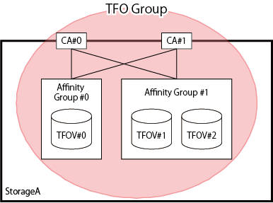
TFO group is a motion unit of failover on one device and a group for which the connection configuration, policy, status and maintenance required to perform failover is consolidated. TFO group includes one or more CA ports and volumes allowed to access those CA ports. The example of TFO group is shown in "Figure 9.2 Example of TFO Group".
Figure 9.2 Example of TFO Group
TFO group has the following status. The TFO status changes with execution of failover or failback:
Point
The input conditions for the TFO group name are as follows:
The 1-16 characters which are alphanumeric characters "A-Z, a-z, 0-9" and special characters. However, ", ? " ' \ * %" cannot be used.
TFO Status | Meaning |
|---|---|
Active | Indicates an active side. Accessible from Management Server. |
Standby | Indicates a standby side. Inaccessible from Management Server. |
If default TFO status is Active in creating an environment, the TFO group is called "Primary TFO Group" and if Standby, "Secondary TFO Group".
Pairing of CA Ports
The Storage Cluster function shares the port parameter in the CA ports of two ETERNUS Disk storage systems, controls the Link status of each CA port, and achieves the failover.
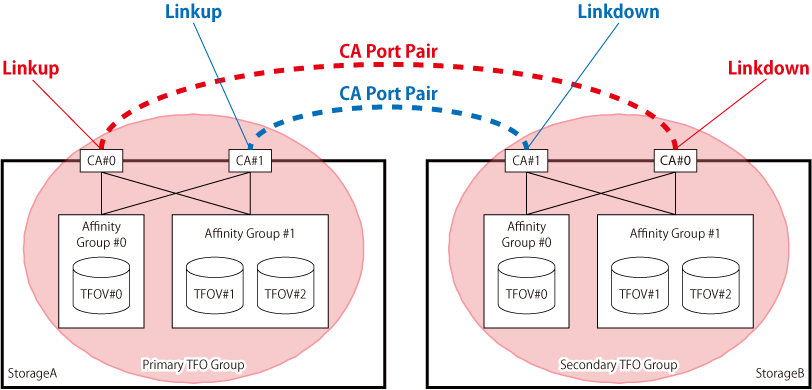
The CA ports included in one TFO group shares one port parameter with the CA ports included in the other TFO group between storage systems. This sharing operation is referred to as "Pairing of CA ports". Also, a pair of CA ports sharing port parameter is referred to as "CA port pair".
For FC configurations, WWPN/WWNN is shared. By pairing CA ports, WWPN/WWNN of the CA port in the Primary Storage is automatically configured as a logical WWPN/WWNN to the CA port in the Secondary Storage and the CA port in the Secondary Storage is Linkdown.
For iSCSI configurations, iSCSI name and iSCSI IP address are shared. By pairing CA ports, the CA port in the Secondary Storage is Linkdown. After that, by setting the iSCSI name and iSCSI IP address of the CA port in the Primary Storage to the CA port in the Secondary Storage manually, the iSCSI name and iSCSI IP address can be shared.
The image of CA port pair is shown in "Figure 9.3 Example of CA Port Pair".
Figure 9.3 Example of CA Port Pair
Automatic Failover
Automatic Failover is a function that makes the Secondary TFO Group active automatically when any failure is detected in an ETERNUS Disk storage system in which the Primary TFO Group exists.
To perform Automatic Failover, Storage Cluster Controller connected with management LAN is required.
"Figure 9.4 Behavior of Automatic Failover When Storage Device Is Downed (for FC Configuration)" shows an image that Storage A (Primary Storage) is down and a failover to Storage B (Secondary Storage) is performed when Storage A and Storage B are in use.
"Figure 9.5 Behavior of Automatic Failover When CA Port Is Linked Down (for FC Configuration)" shows an image that all the CA ports belonging to the Primary TFO Group are linked down because of CA port failure or connection failure in Storage A (Primary Storage) and a failover to Storage B (Secondary Storage) is performed when Storage A and Storage B are in use.
These are examples for FC configurations. For iSCSI configurations, the iSCSI name and iSCSI IP address are set for the CA port and the switch becomes the network switch.
Figure 9.4 Behavior of Automatic Failover When Storage Device Is Downed (for FC Configuration)
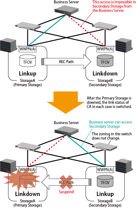
Figure 9.5 Behavior of Automatic Failover When CA Port Is Linked Down (for FC Configuration)
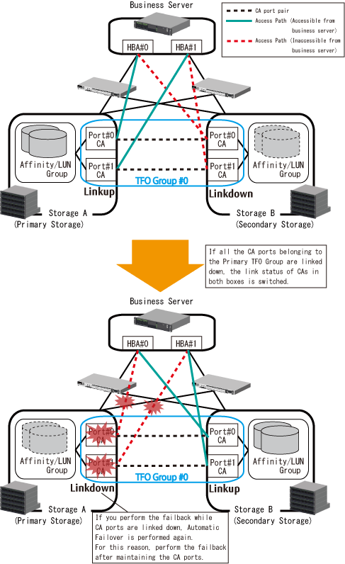
In accordance with link switchover of each CA port, the status of TFO group is also automatically switched, so that the volumes in the Secondary TFO Group become accessible.
Note
When the storage device is an ETERNUS DX S4/S3 series (excluding the ETERNUS DX8900 S4), an ETERNUS AF S2 series, or an ETERNUS DX200F, or when the storage device is an ETERNUS DX8900 S4 whose firmware version is earlier than V11L20, if a Linkdown of the REC path between the Primary Storage and the Secondary Storage and a Linkdown of the CA port that connects with business servers occur at the same time when multiple switches fail, Automatic Failover cannot be performed during a CA port Linkdown. Configure the system settings to separate the switches for the REC path and for the business server so that a simultaneous Linkdown does not occur.
Automatic Failback
Automatic Failback is a function in which the Primary TFO Group automatically becomes "Active" when recovering from the failure of ETERNUS Disk storage system with the Primary TFO Group detected.
Releasing and Recovering TFO Pairs
These operations are performed during a maintenance procedure when a RAID failure, a RAID close, or a bad sector occurs, or when the session status of the TFO pair becomes "Error Suspend". Select a target pair from the list of volume pairs for which Storage Cluster is available.
Point
When releasing TFO pairs
Release the TFO pairs of all TFOVs that belong to the failed RAID group so that the RAID group can be maintained.
When recovering TFO pairs
Recover the TFO pairs of all TFOVs that belong to the failed RAID group. By recovering the TFO pairs, a synchronization between the paired volumes are performed with the initial copy. Refer to "Table 9.6 Time Required for Initial Copy (Standard Value of 1 TB Physical Capacity Volume)" for the time required for an initial copy.
Deconstruction of Storage Cluster Environment
If such a trouble as requires device replacement occurs and an ETERNUS Disk storage system should be replaced, deconstruct the Storage Cluster environment.
Delete TFO groups to deconstruct the Storage Cluster environment.
For FC configurations, when deleting TFO groups, you can select either of the following actions to handle WWPN/WWNN of the CA port for the Secondary Storage:
Return the Secondary Storage CA port to its original WWPN/WWNN.
Return the Secondary Storage CA port not to its original WWPN/WWNN but continue to use the logical WWPN/WWNN.
If Step "a" is selected, it does not compete with the WWPN/WWNN of the Primary Storage CA port.
If Step "b" is selected, the device operated as the Primary Storage can be replaced while the Secondary Storage is accessible from the Management Server.
Note
For FC configurations
If both the Primary Storage CA port and the Secondary Storage CA port get active, their WWPN/WWNN competes with each other, possibly causing data corruption. Therefore, when selecting Step "b", keep the following rules:
Do not delete the TFO group before making sure that the Primary Storage CA port is physically disconnected from SAN.
Do not connect to SAN the ETERNUS Disk storage system that had the Primary TFO Group deleted.
For iSCSI configurations
The set values for the iSCSI name and the iSCSI IP address remain unchanged. Therefore, keep the following rules:
Check whether the iSCSI IP address is not a duplicate in the same SAN. If it is a duplicate, do not delete the TFO group before changing the iSCSI IP address.
Do not delete the TFO group before making sure that the storage device in the standby side is physically disconnected from SAN.
Control of Link Status of Primary/Secondary Storage CA Ports
Depending on pairing of CA ports and failover, the port parameter and Link status of CA ports are changed. The device whose Link status is Linkup is accessible from the Management Server.
For FC configurations, the value of WWPN/WWNN is changed by pairing CA ports.
For iSCSI configurations, manually setting the parameter of the iSCSI CA port of the Secondary Storage to match that of the Primary Storage after a CA port pairing can control the Link status.
Change in Link status of each CA port with CA port pairing and failover/failback operations are shown in "Table 9.3 Change in Link Status of CA Port (for FC Configurations)" and "Table 9.4 Change in Link Status of CA Port (for iSCSI Configurations)".
Primary Storage | Timing | Secondary Storage | ||
|---|---|---|---|---|
WWPN/WWNN | Link Status | Link Status | WWPN/WWNN | |
WWPN/WWNN of the Primary Storage side | Linkup | Pre-CA port pairing | Linkup | WWPN/WWNN of Secondary Storage side |
Post-CA port pairing | Linkdown | WWPN/WWNN of the Primary Storage side | ||
Linkdown | Primary Storage stops | |||
Under failover | ||||
Failover completed | Linkup | |||
Primary Storage recovered | ||||
Failback started | ||||
Under failback | Linkdown | |||
Linkup | Failback completed | |||
Storage Cluster deconstructed (*1) | Linkup | WWPN/WWNN of the Secondary Storage side | ||
*1: When returning the WWPN/WWNN of the Secondary Storage CA port to its original status.
Primary Storage | Timing | Secondary Storage | ||
|---|---|---|---|---|
iSCSI Information | Link Status | Link Status | iSCSI Information | |
iSCSI information of the Primary Storage side | Linkup | Pre-CA port pairing | Linkup | iSCSI information of the Secondary Storage side |
Post-CA port pairing | Linkdown | |||
Parameter setting of iSCSI CA port of the Secondary Storage side | iSCSI information of the Primary Storage side | |||
Linkdown | Primary Storage stops | |||
Under failover | ||||
Failover completed | Linkup | |||
Primary Storage recovered | ||||
Failback started | ||||
Under failback | Linkdown | |||
Linkup | Failback completed | |||
Parameter setting of iSCSI CA port of the Secondary Storage side | iSCSI information of the Secondary Storage side | |||
Storage Cluster deconstructed | Linkup | |||
Storage Cluster Controller
To perform Automatic Failover, Storage Cluster Controller connected with management LAN is required.
Two ETERNUS Disk storage systems use a REC Path for checking the living confirmation. If the REC Path is disconnected, even if the two ETERNUS Disk storage systems are running, failover may be performed by false recognition. To prevent this false recognition, install Storage Cluster Controller to communicate with both the Primary Storage and the Secondary Storage with management LAN.
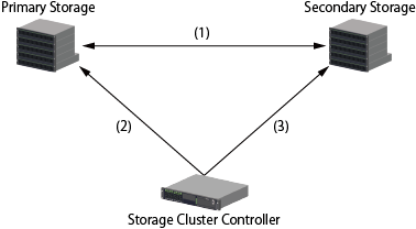
The example of structure between both the Primary Storage and the Secondary Storage and Storage Cluster Controller is shown in "Figure 9.6 Structure Example of Life Check via Storage Cluster Controller". In this structure example, communication status, device status and timing of Automatic Failover are shown in "Table 9.5 Timing of Automatic Failover Operation".
Figure 9.6 Structure Example of Life Check via Storage Cluster Controller
Number | Communication Status | Device Status | ||||
|---|---|---|---|---|---|---|
(1) | (2) | (3) | Primary Storage | Secondary Storage | Timing of Automatic Failover Operation and Status Change | |
1 | Y | Y | Y | Alive | Alive | N/A |
2 | N | Y | Y | |||
3 | Y | N | Y | |||
4 | Y | Y | N | |||
5 | N | N | Y | Down | A Primary Storage: Active -> Standby | |
6 | N | Y | N | Alive | Down | N/A |
7 | Y | N | N | Alive | ||
8 | N | N | N | Down | Down | N/A (all blocked) (*1) |
Y: Communication enabled status
N: Communication disabled status
*1: During a disaster, when recreating a network environment that includes communication of Storage Cluster Controller, the communication from Storage Cluster Controller may be temporarily disconnected and an overall blockage may occur.
Note
Automatic Failover does not operate in the following cases:
For FC configurations
When "route (1) between the Primary Storage and the Secondary Storage" failed 10 seconds after "route (2) between the Primary Storage and the Storage Cluster Controller" had failed.
When "route (2) between the Primary Storage and the Storage Cluster Controller" failed three seconds after "route (1) between the Primary Storage and the Secondary Storage" had failed.
For iSCSI configurations
When "route (1) between the Primary Storage and the Secondary Storage" failed 20 seconds after "route (2) between the Primary Storage and the Storage Cluster Controller" had failed.
When "route (2) between the Primary Storage and the Storage Cluster Controller" failed seven seconds after "route (1) between the Primary Storage and the Secondary Storage" had failed.
Storage Cluster Controller and each monitored ETERNUS Disk storage system monitor each other. Therefore, if the Storage Cluster Controller and the managed ETERNUS Disk storage systems are placed in the same building, the following trouble could occur:
If the building is exposed to disaster, all the paths are blocked and failover gets disabled.
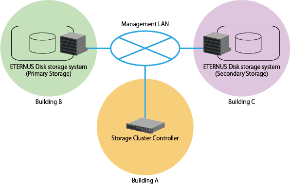
To prevent the above trouble, it is recommended to place the Storage Cluster Controller and each monitored ETERNUS Disk storage system in separate buildings respectively. The location example is shown in "Figure 9.7 Location Example of Storage Cluster Controller and Monitored ETERNUS Disk Storage Systems".
Also, the Storage Cluster Controller can be located on the same server as Management Server.
Figure 9.7 Location Example of Storage Cluster Controller and Monitored ETERNUS Disk Storage Systems
