A mutual standby operation can be achieved by defining several virtual interfaces and by configuring each resource as a separate userApplication.
Starting process is equivalent to the standby operation, except that the mutual standby operation contains various userApplications. For details, please refer to "5.1.1.1 Starting".
Usually, userApplication communicates with the remote system using the virtual interface on each node. If a failure (such as panic, hang-up, or transfer path failure) occurs on the operating node, the virtual interface comprised in that corresponding node is passed over to the standby node. With an application allowing reconnection, it takes over the connection of the operating node.
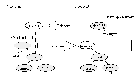
Figure 5.18 Mutual standby configuration diagram in Fast switching mode shows the mutual standby configuration diagram of duplicated operation in Fast switching mode. The takeover of an address, etc. is performed in the same way as for the active standby configuration. For information, see Section "5.1.1.1.1 Fast switching mode".
Figure 5.18 Mutual standby configuration diagram in Fast switching mode

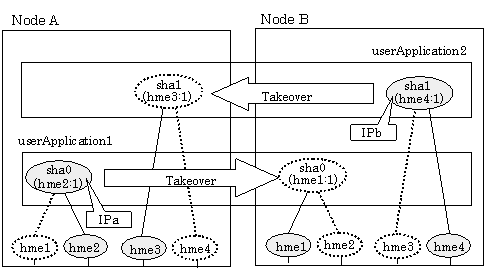
Figure 5.19 Mutual standby configuration diagram in NIC switching mode (NIC non-sharing) shows the mutual standby configuration diagram in NIC switching mode (NIC non-sharing). The takeover of an address, etc. is performed in the same way as for the active standby configuration. For information, see Section "5.1.1.1.2 NIC switching mode".
Figure 5.19 Mutual standby configuration diagram in NIC switching mode (NIC non-sharing)

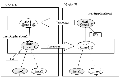
Figure 5.20 Mutual standby configuration diagram in NIC switching mode (NIC sharing) shows the mutual standby configuration diagram in NIC switching mode (NIC sharing). The takeover of an address, etc. is performed in the same way as for the active standby configuration. For information, see Section "5.1.1.1.2 NIC switching mode".
Figure 5.20 Mutual standby configuration diagram in NIC switching mode (NIC sharing)

The fail-back is performed in the same way as for the active standby configuration. For more information, see "5.1.1.3 Fail-back".
Stopping operation is equivalent to active standby connection. For detail, see "5.1.1.4 Stopping".