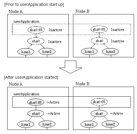
With userApplication startup, the takeover virtual interface (sha0:65) over operating node will be activated, enabling communication using the takeover virtual IP address.
When operating, Fast switching mode uses the Redundant Line Control function to communicate with the remote system.
Note that the virtual interface (such as sha0) is inactive just after GLS starts up. The virtual interface will be active after the first startup of userApplication. Once it becomes active, regardless of stopping or restarting userApplication, it remains to be active until the system stops.
Note
When communicating with the other network using the virtual interface of Fast switching mode, or activating the virtual interface prior to userApplication startup, use hanetparam command to set the activation timing.
For detail, refer to "7.6 hanetparam Command".
For description of setup, refer to "D.1 Changing Methods of Activating and Inactivating Interface".
Figure 5.2 Startup behavior of Fast switching mode shows behavior of Fast switching mode after starting up
Figure 5.2 Startup behavior of Fast switching mode
NIC switching mode has the following address takeover functions. Select a function to be used depending on your operation.
Logical address takeover
Using the logical address takeover function allows a LAN to have several virtual IP addresses. Ordinary communication will be done via a physical IP address, and a communication through GLS will be done via the virtual IP addresses.
For the remote system device to make a connection, a physical IP address should be specified as the connection address. Then, the remote system device can directly connect to the active or standby node and manage each of the nodes regardless of the status transition of the userApplication.
For this function, two IP addresses are assigned to one physical interface. To use a TCP/IP application that requires only one IP address to be specified, use the physical address takeover function I or II.
Physical IP address takeover I
Use the Physical IP address takeover function I for a GLS network and an ordinary network to exist in a same LAN, sharing an IP address allocated to a physical interface.
This function allows a connection to be made for each of the active and standby nodes independently. However, IP address of the standby node changes according to the status transition of the userApplication. Thus, when clusters are switched, the TCP connection to the standby node is cleared. For the communication target device to make a connection again, the connection IP address must be changed.
Physical IP address takeover II
Use the Physical IP address takeover function II to use a LAN only for GLS networking. In this case, no connection can be made to the standby node because the LAN of the standby node is inactivated. Another LAN must be provided to make a connection.
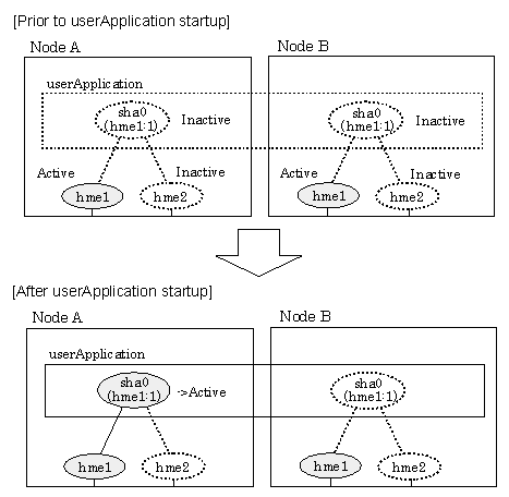
Figure 5.3 Startup behavior of NIC switching mode (take over logical IP) shows the active standby configuration diagram of duplicated operation in NIC switching mode (logical IP address takeover function). The operation in this figure is as follows: On active node A, the logical interface (hme1:1) of the secondary interface (hme1) is assigned the takeover virtual IP address (IP-A) and activated. If switching occurs due to a failure, the takeover virtual interface (hme1:1) that has been assigned the takeover IP address (IP-A) is inactivated. Then, on standby node B, the logical interface (hme0:1) that has been assigned the takeover IP address (IP-A) on the already activated primary interface (hme0) is activated.
Figure 5.3 Startup behavior of NIC switching mode (take over logical IP)
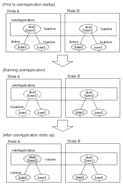
For taking over physical IP address I, activate the physical interface (hme1) for operating node and standby node when the Redundant Line Control function starts up. After the userApplication starts, it will activate the physical interface by allocating a takeover IP address to the physical interface on the operating node. At this time, a physical interface (hme1) over the standby node remains to be inactive.
Figure 5.4 Startup behavior of NIC switching mode (takeover physical IP address I) shows a startup behavior of takeover physical IP address I
Figure 5.4 Startup behavior of NIC switching mode (takeover physical IP address I)
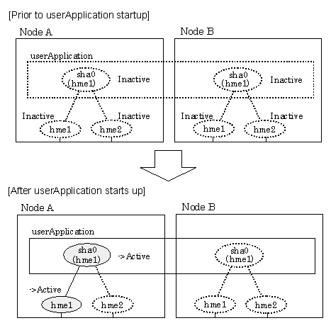
For taking over physical IP address II, it does not activate the physical interface (hme1) for both operating node and standby node when Redundant Line Control function starts up. Instead it allocates a takeover IP address to the physical interface (hme1) on the operating node and then it activates the physical interface. In this case, the physical interface (hme1) for standby node remains inactive.
Figure 5.5 Startup behavior of NIC switching mode (takeover physical IP address II) shows a startup behavior of the takeover physical IP address II
Figure 5.5 Startup behavior of NIC switching mode (takeover physical IP address II)
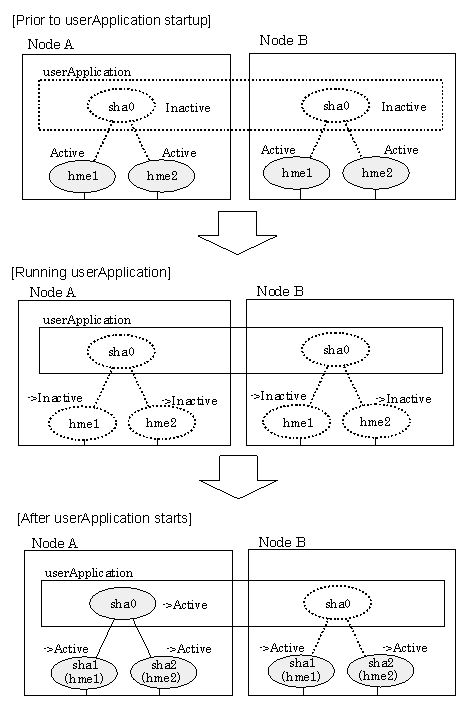
By starting userApplication, the take over virtual interface (sha0) over operating node becomes active allowing communication using the take over virtual IP address. When operating, GS/SURE linkage mode uses the Redundant Line Control function to communicate with the remote system.
Figure 5.6 Startup behavior of GS/SURE linkage mode shows startup behavior of GS/SURE linkage mode
Figure 5.6 Startup behavior of GS/SURE linkage mode
During normal operation, the system communicates with the remote system using Redundant Line Control function on the operating node.
If a failure (panic, hang-up, or line failure) occurs on the operating node, Redundant Line Control function switches the resources to the standby node. Then, applications make reconnection to take over the communication from the operating node.
Figure 5.7 Switching behavior of Fast switching mode indicates switching behavior of Fast switching mode.
In the following figure, the takeover IP address (IPa) is allocated to the takeover virtual interface (sha0:65) for operating node A. Then it activates the takeover virtual interface. When switching the interface due to failures in the transfer path, the takeover virtual interface (sha0:65) for operating node A becomes inactive. Then in standby node B, the takeover virtual interface (sha0:65), which has allocated the takeover IP address (IPa) becomes active. Note that the virtual interface (sha0) in node A remains unchanged.
Figure 5.7 Switching behavior of Fast switching mode
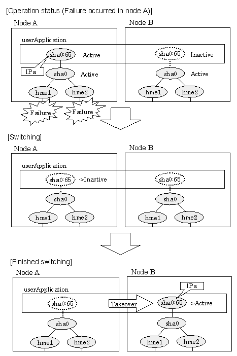
Figure 5.8 Switching behavior of NIC switching mode (takeover logical IP) illustrates switching behavior of NIC switching mode (logical IP address takeover function).
In the following figure, the takeover virtual IP address (IPa) in the operating node A is allocated to the logical interface (hme2.1) for the secondary interface. Once IPa is allocated, the logical interface (hme2.1) for the secondary interface turns into activate state.
When switching the node due to failure in the transfer routes, NIC switching mode inactivates the logical virtual interface which has allocated the takeover IP address (IPa) in the operating node A. Then it allocates the takeover IP address to the primary interface (hme1) and finally activates the logical interface (hme1:1).
Figure 5.8 Switching behavior of NIC switching mode (takeover logical IP)
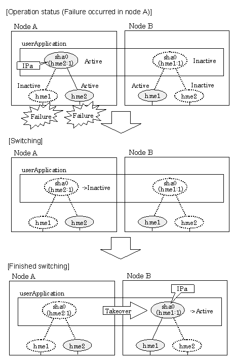
Figure 5.9 Switching behavior of NIC switching mode (takeover physical IP I) (continues) and Figure 5.10 Switching behavior of NIC switching mode (takeover physical IP I) illustrate switching behavior of NIC switching mode (takeover physical IP address I).
In the following figure, the takeover virtual IP address (IPa) in the operating node A is allocated to the secondary interface. Once IPa is allocated it turns into activate state.
When switching the node due to a failure in the transfer routes, temporally inactivate the primary interface (hme1), which has been active in the standby node B. Then it allocates the takeover IP address (IPa) to activate the primary interface (hme1). Once the primary interface activates, different IP address is allocated to the secondary interface (hme2) by means of inactivating hme2.
Figure 5.9 Switching behavior of NIC switching mode (takeover physical IP I) (continues)
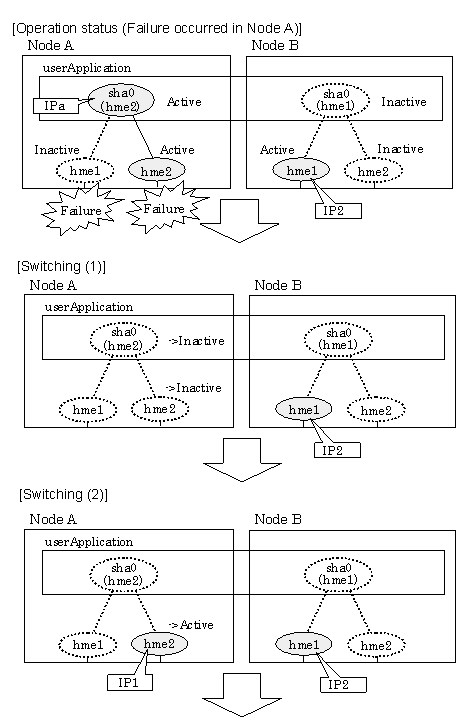
Figure 5.10 Switching behavior of NIC switching mode (takeover physical IP I)
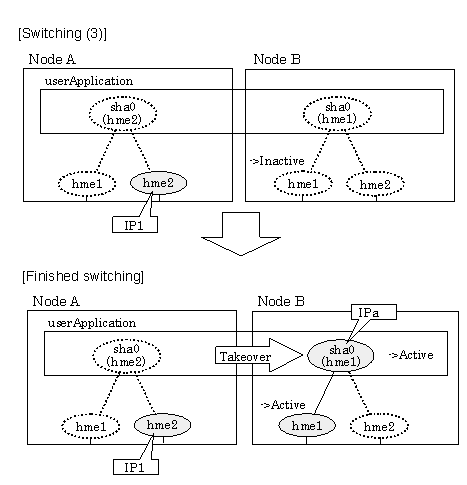
Figure 5.11 Switching behavior of NIC switching mode (takeover physical IP address II) illustrates switching behavior of NIC switching mode (takeover physical IP address II).
In the following figure, the takeover IP address (IPa) in the operating node A is allocated to the secondary interface. Once IPa is allocated it turns into activate state.
When switching the node because of a failure in the transfer path, the standby node B turns to be active by allocating the takeover IP address (IPa) to the primary interface (hme1). After the IP address is successfully passed over to the standby node, the secondary interface (hme2), which previously owned the takeover IP address (IPa) in node A becomes inactive.
Figure 5.11 Switching behavior of NIC switching mode (takeover physical IP address II)
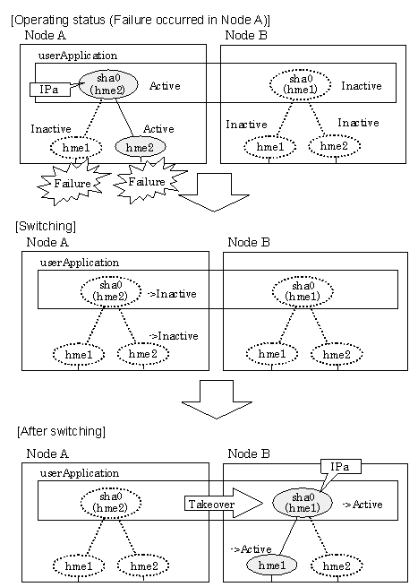
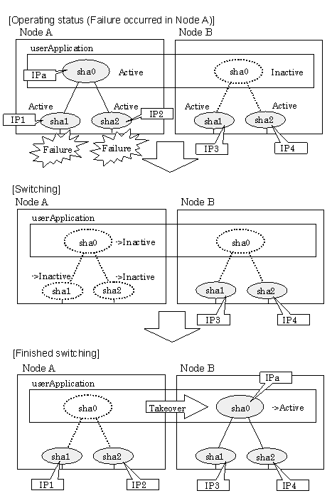
Figure 5.12 Switching behavior of GS/SURE linkage mode illustrates switching behavior of GS/SURE linkage mode.
In the figure below, a takeover virtual interface (sha0) is activated in the operating node. When switching occurs due to a failure, deactivate takeover virtual interface (sha0) and the virtual interfaces (sha1, sha2) in node A. Then, GS/SURE linkage mode activates the virtual interfaces (sha1, sha2). On standby node B, it activates the takeover virtual interface (sha0), which bundles the virtual interfaces (sha1, sha2).
Figure 5.12 Switching behavior of GS/SURE linkage mode
The following shows a procedure of performing fail-back after failure recovery if node switching occurs.
1) Make recovery for a node on which a failure has occurred.
If switching has occurred due to panic or hang-up, reboot the node that has panicked or hanged up.
If switching has occurred due to a line failure, restore the line to a normal status (perform necessary work such as reconnecting a cable, powering on a HUB again, and replacing a faulty HUB).
2) Restore the original operation status.
Restore the original operation status by performing fail-back operation for userApplication.
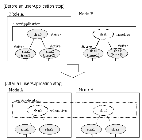
Figure 5.13 Stopping behavior of Fast switching mode illustrates stopping process of userApplication.
Figure 5.13 Stopping behavior of Fast switching mode
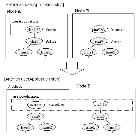
Figure 5.14 Stopping process of NIC switching mode (logical IP takeover) illustrates stopping process of userApplication for logical IP takeover.
Figure 5.14 Stopping process of NIC switching mode (logical IP takeover)
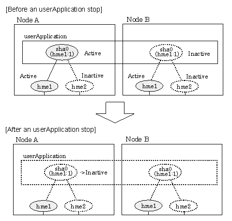
Figure 5.15 Stopping process of NIC switching mode (physical IP takeover) illustrates stopping behavior of userApplication for the physical IP takeover I.
Figure 5.15 Stopping process of NIC switching mode (physical IP takeover)
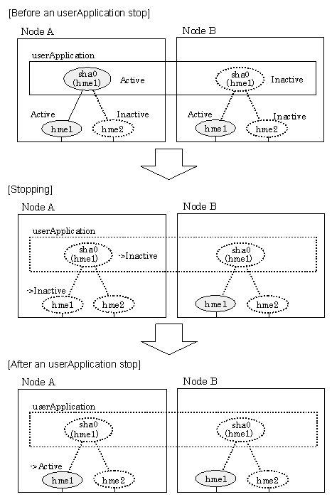
Figure 5.16 Stopping process of NIC switching mode (physical IP takeover II) illustrates stopping behavior of userApplication for the physical IP takeover II.
Figure 5.16 Stopping process of NIC switching mode (physical IP takeover II)
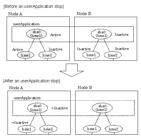
Figure 5.17 Stopping process of GS/SURE linkage mode illustrates stopping behavior of userApplication.
Figure 5.17 Stopping process of GS/SURE linkage mode
