In cluster system, Redundant Line Control function supports the following operation modes:
Active standby system (1:1 and N:1)
Mutual standby system
Cascade system
Priority transfer system
How cluster failover is dealt with in each mode is shown below.
Mode | Active Standby System | Active Standby System | Mutual standby System | Cascade System | Priority transfer system | Duplicate transfer path for SIS |
|---|---|---|---|---|---|---|
Fast switching mode | A | A | A | A | A | X |
RIP mode | X | X | X | X | X | X |
Fast Switching/RIP mode | X | X | X | X | X | X |
NIC switching mode | A | A | A | A | A | A |
GS/SURE linkage mode | A | X | X | X | X | X |
[Meaning of the symbols] A: Supported X: Not supported
Virtual IP addresses allocated to virtual interfaces are taken over if a cluster switching event occurs. GLS does not provide any function to support MAC address takeover and system node name takeover. A physical interface used for GLS cannot be used to configure a cluster resource (Takeover IP address and Takeover MAC address). Table 5.2 Supported cluster take over information indicates the support status of each takeover function.
Cluster Operation mode | IP address | MAC address | IP address | IP address | IP address |
|---|---|---|---|---|---|
1:1 Active standby | A | X | X | X | X |
N:1 Active standby | A | X | X | X | X |
Mutual standby | A | X | X | X | X |
Cascade | A | X | X | X | X |
Priority transfer | A | X | X | X | X |
[Meaning of the symbols] A: Supported X: Not supported B: No match
Note
Configuring GLS as Priority transfer, one of the cluster operation, follows the same procedure for configuring Cascade operation.
When using Fast switching mode, you need a host running Fast switching mode as an associate host other than a node configuring a Cluster system. Failover of Gls resource may fail if there is only one Cluster system configuring nodes on the transfer route monitoring host due to simultaneous detection of transfer route failure on operation node and standby node.
Scalable configuration as well as standby configuration in High-availability scalable settings are not supported.
When switching the node in both Fast Switching and NIC switching mode, do not use IPv6 address as a take over virtual interface if immediate communication is required. If IPv6 address is used, it takes approximately 30 seconds to restore communication after switching the node. For detail, see "D.2 Trouble shooting".
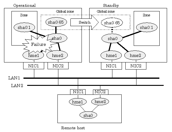
The logical virtual interface and IP address allocated in the Solaris zone cannot be taken over along with cluster switching. If a failure occurs on all the transmission routes of the operating node, a communication session between the Solaris zone and Global zone fails.
Figure 5.1 Cluster Switching for the virtual interface shows an example of cluster switching for the virtual interface.
Figure 5.1 Cluster Switching for the virtual interface

The logical unit number for the virtual interface for cluster switching is 65 or later. (sha0:65, sha0:66)