An example showing the creation of the operation task procedure as an Automated Operation Process is shown below:
An application to stop the server is made, the approver checks the application content then either approves or rejects the application. If the application is approved and the server is stopped, the confirmer checks the results.
The applicant enters the host name or IP address of the server to be stopped, and the reason for the application, in an application form. Next, the approver checks the application content then approves the application if there are no problems with it. If there are problems with the application content, the approver rejects the application. If the application is approved, the server is stopped, the confirmer checks the execution results in a confirmation form, then selects processing for a normal or abnormal end. In this way, the transition of the Automated Operation Process occurs according to human decision making.
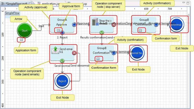
The procedure that is used to create the Automated Operation Process is shown below.
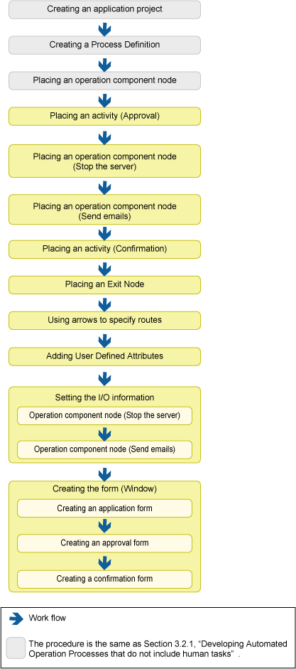
Check the application content, and add Activity to approve or reject.
Select Activity in the Basic tab in Palette. With the Process Definition Editor, add the activity by pointing and clicking in the area where it should be placed.
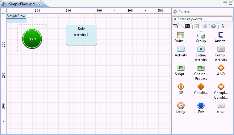
The Activity Node is added.
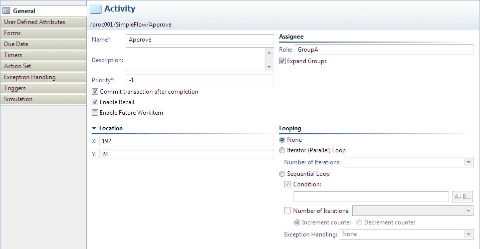
In the Process Definition Editor, click the activity, then click the Properties >> General tabs. The Name field value changes to "Approval". Additionally, in the Person in charge >> Role field, enter the group that the user that will operate (approve or reject application) the activity belongs to. Here, "GroupA" has been set.
Point
When the transition occurs for the processing of the activity that was placed here, the task will be assigned to the user belonging to the group set for Person in charge >> Role (here, this will be "GroupA").
It is possible to configure settings to send an email to notify the fact that the task has been assigned (this is a setting in the Web console). Refer to "8.5 Setting Up Email Notification" for information on the configuration method.
Add the operation component for stopping the server.
Select Stop the server in the Server operations tab in Palette. With the Process Definition Editor, add the operation component node by pointing and clicking in the area where it should be placed.
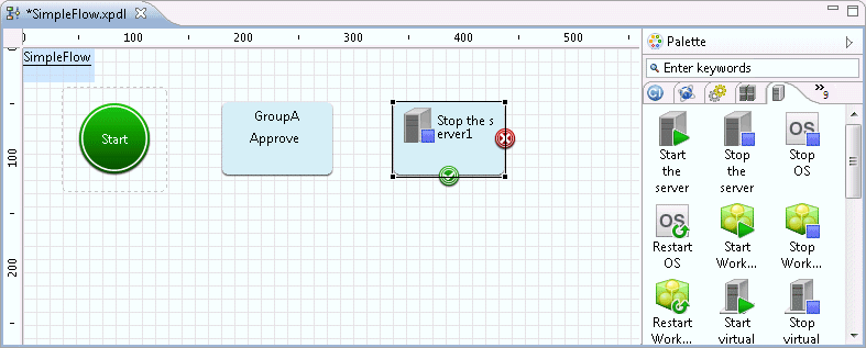
The operation component node (Stop the server) is added.
If the application content is invalid, an operation component is added for an email that notifies the fact that the application was rejected.
Select the Send emails button in the Email Operations tab in Palette. With the Process Definition Editor, add the operation component node by pointing and clicking in the area where it should be placed.

The operation component node (Send emails) is added.
Add the activity for checking the operation component execution result.
Select Activity in the Basic tab in Palette. With the Process Definition Editor, add the activity by pointing and clicking in the area where it should be placed.
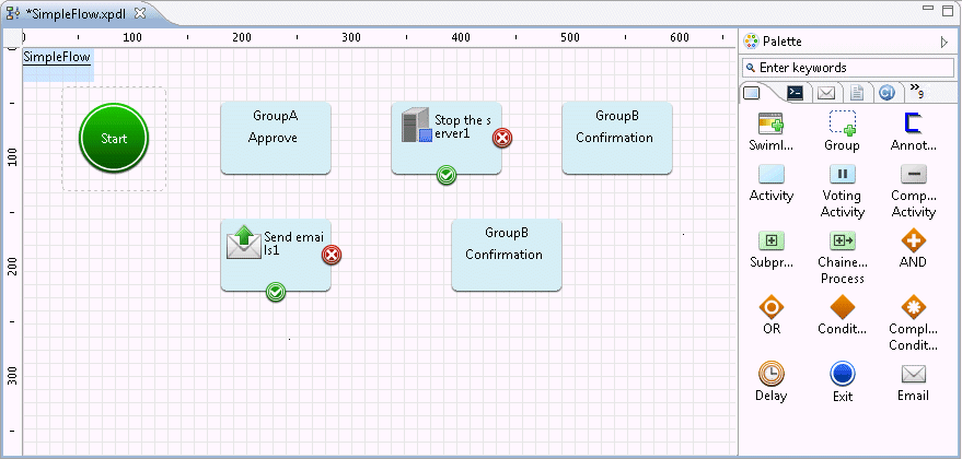
The Activity Node is added.
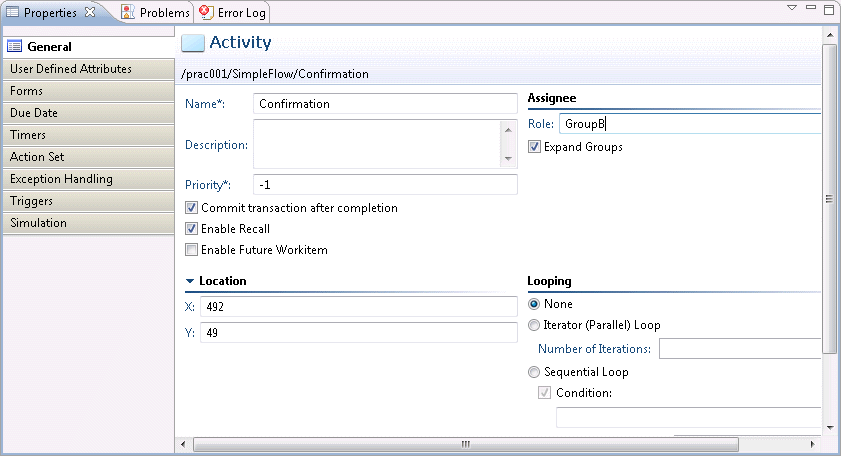
In the Process Definition Editor, click the activity, then click the Properties >> General tabs. The Name field value changes to "Confirmation". Additionally, in the Person in charge >> Role field, enter the group that the user that will operate (check the execution result) the activity belongs to. Here, "GroupB" has been set.
Add an Exit Node that indicates the terminal point of the Automated Operation Process.

The Exit Node is added.
Here, two Exit Nodes are added - one for when the application was rejected, and one for when the operation component node execution results were normal or abnormal. Change the node names as follows:
Exit1 | Reject |
Exit2 | Normal termination |
Exit3 | Abnormal termination |
Each node is joined by an arrow.
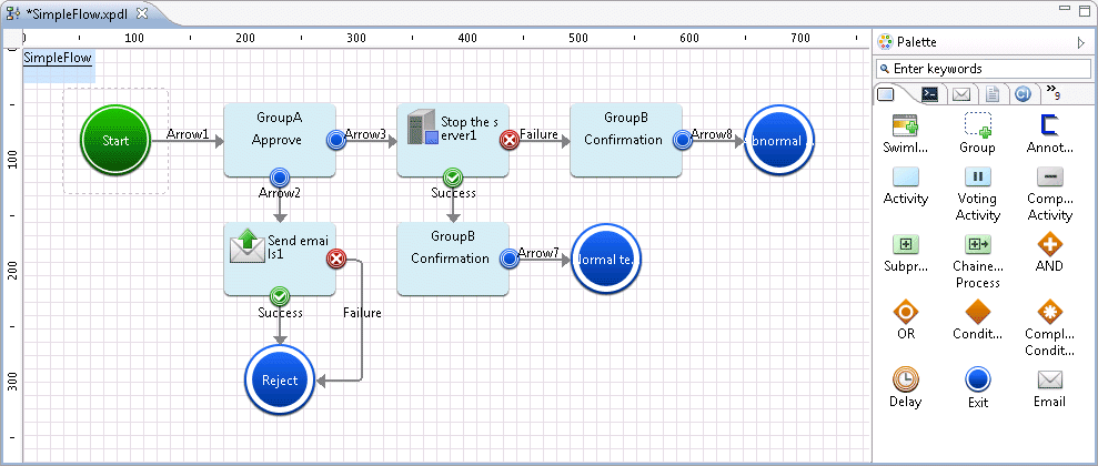
Change the arrow names as follows:
Node name | Arrow name before change | Arrow name after change |
|---|---|---|
Start | Arrow1 | Start |
Approvals | Arrow2 | 2: Reject |
Arrow3 | 1: Approved | |
Send emails 1 | Successful | Send normal |
Failure | Send abnormal | |
Stop the server 1 | Successful | Results confirmation(Normal) |
Failure | Results confirmation(Abnormal) | |
Confirm | Arrow7 | Normal termination |
Confirm | Arrow8 | Abnormal termination |
Display on the Web console
The "Application" arrow from the Start Node appears as the Start button in the Web console. By clicking this Start button, the application to "Stop the server" is executed.
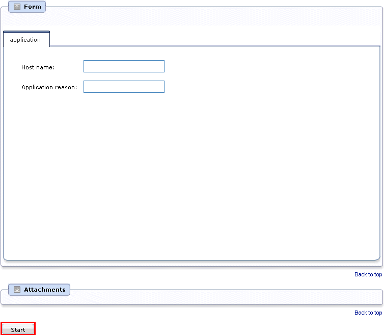
The "1: Approved" and "2: Reject" arrows from the "Approvals" activity are displayed in the Web console as the 1: Approved button and the 2: Reject button. By clicking the 1: Approved button, the application to "Stop the server" is approved and processing transition occurs for the next operation component node ("Stop the server"). When the 2: Reject button is clicked, processing transitions to the "Exit1" node by way of the "Send emails" and "Exit" nodes, and then, the process terminates.

Point
Display order for buttons
The arrow name is used as the button name for the transition of status for activities on the Web console. When multiple arrows are drawn from the activity and the arrows are given names using alphabets, the button order will be displayed in the alphabetic order.
[Process definition]

Consider the process definition displayed above. Here, if two arrows with the names OK and NG are drawn from the activity, the buttons will be displayed in the following order on the Web console.
[Display on the Web console]

To change the order of buttons on the Web console, add a number at the beginning of the arrow names so that the buttons can be displayed in the ascending order .
[Process definition]
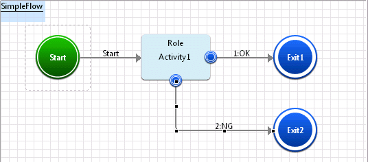
[Display on the Web console]

Similarly, if English is used for arrow names, add a number to the start of the arrow name so that the buttons can be displayed in the ascending order, as displayed below.
[Process definition]
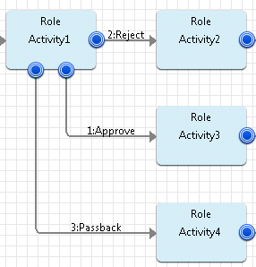
[Display on the Web console]

In this Automated Operation Process, input specifying the host name as the "Stop the server" operation component input information, and for the input of the reason for the application from form. Here, Create hostname entered from form, and variables(UDA) to store the reason for the application.
Click the Properties >> User-Defined Attributes tabs. Click the Add button to add the User-Defined Attribute (UDA).

Change the name of the User-Defined Attribute (UDA) that was added.
Click the Add button again to create the following types of User-Defined Attribute (UDA):
Name | Type | Initial Value |
|---|---|---|
hostname | STRING | |
service | STRING |

Set up the I/O information required to execute the operation component node placed.
Click the operation component node (Stop the server) on the Process Definition Editor. Click the Properties >> IO Setting >> Input Data tabs.
For the "Stop the server" component, specify the host name.
hostname: Host name of the server to be stopped
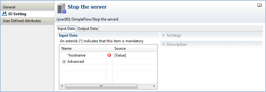
From the Input Data section list, select hostname.
The Settings and Description fields will be displayed in the right half of the Properties view.
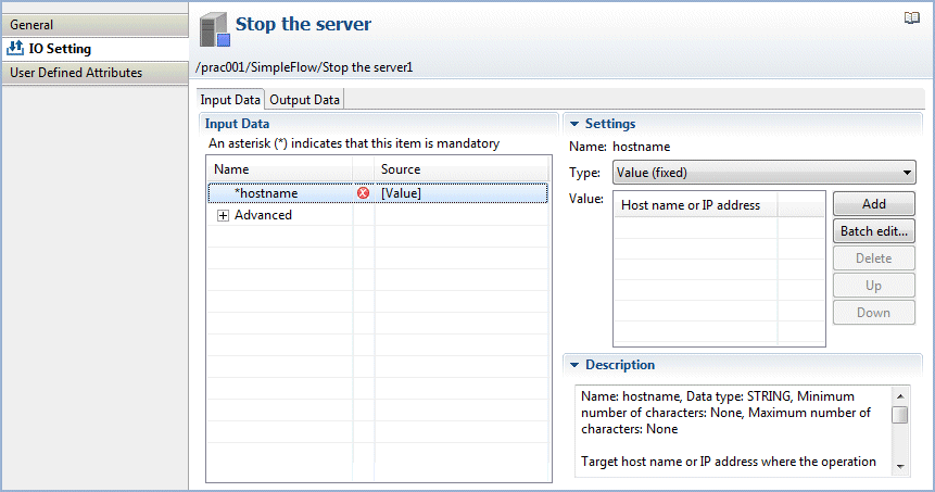
From the Type combo-box, select Variable (uda), and from the Variable list, select the variable (UDA) that will receive the host name. Here, "hostname" is selected as the variable (UDA) that will receive the host name.
The UDA types that can be specified for the operation component input information will depend on the input information data type.
Refer to "3.2.1.7 Setting the I/O Information" for details.
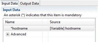
Type: uda
Value: hostname
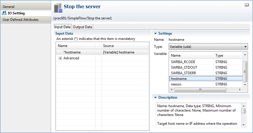
Check that the information has been entered as shown below:
Set the I/O information for the operation component node that was positioned.
Click the operation component node (Send emails) on the Process Definition Editor. Click the Properties >> IO Setting >> Input Data tabs. In the "Send emails" component, specify the following input information:
hostname: Host name or IP address of the (SMTP) server sending emails
fromaddress: Email sender's address
toaddress: Email recipient's address
subject: Email title
text: Email text body
Note
The process instance upper limit size is 4MB. This size is the total of the process instance history information, number of placed nodes, number of UDAs, and stored values. If this size exceeds 4MB because large amounts of data are stored in the UDA while the process instance is being executed, the following message will be output to the custom message and the process instance will end abnormally.
FSP_SW/RB-A_BASE: [ERROR]: 03012: Cannot set data because data exceeds the limit.
If the process instance ends abnormally and the above error message is output, take the following action:
Reduce the size of the value that is output to the UDA by the operation component.
Use a subprocess to balance the processing that is executed in one process instance.
Create the form for assigning the host name as the "Stop the server" operation component input information, and for the input of the reason for the application.
Display on the Web console
The input form created here will be displayed on the Web console as follows:

Refer to "Using Forms" in the Systemwalker Runbook Automation Studio User's Guide, and "Reference for QuickForm UI Widgets" in the Systemwalker Runbook Automation Reference Guide for information on QuickForm.
Operating procedure
Right-click the Start Node, and then select QuickForm >> New from the pop-up menu that is displayed.
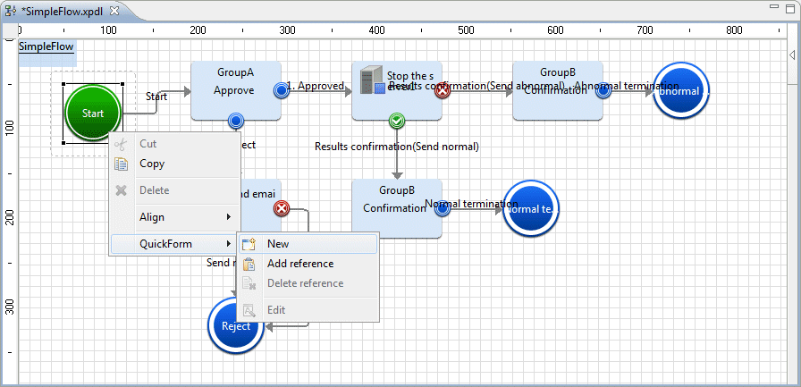
In the New QuickForm dialog, enter a name for the form in the Name field.
Project: /prac001/web (Required)
Name: application (Required)
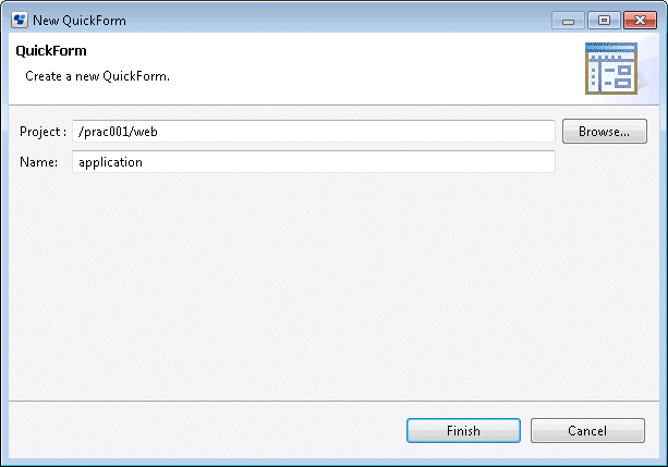
Click the Completed button.
The QuickForm Design Editor will be displayed.
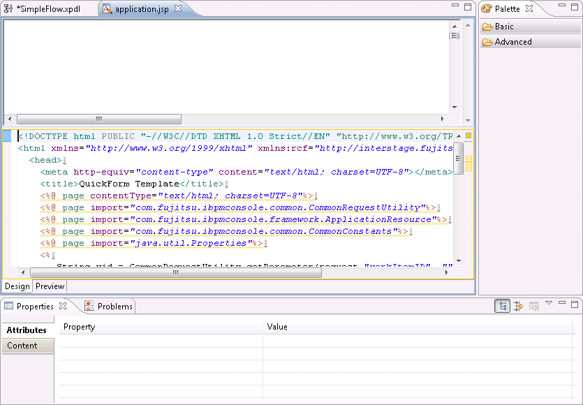
Point
Items of low user frequency in the palette displayed on the right of the QuickForm Design Editor can be hidden using the following steps:
Right-click Palette, then select Customize from the pop-up menu.
The Customize Palette dialog box will be displayed.
Select the item to be hidden from the tree on the left.
Select the Hide button on the right.
Click the OK button.
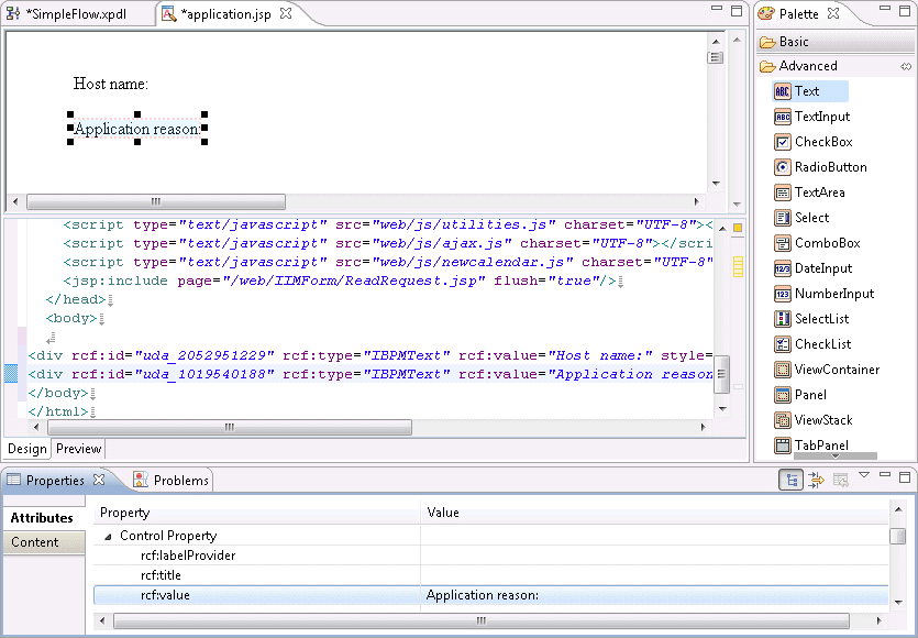
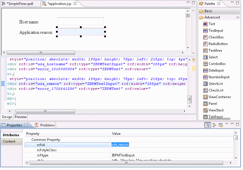
Select the Text item in the Palette >> Advanced folder. Click the location where you want to position the item on the Design Editor to add the Text item.
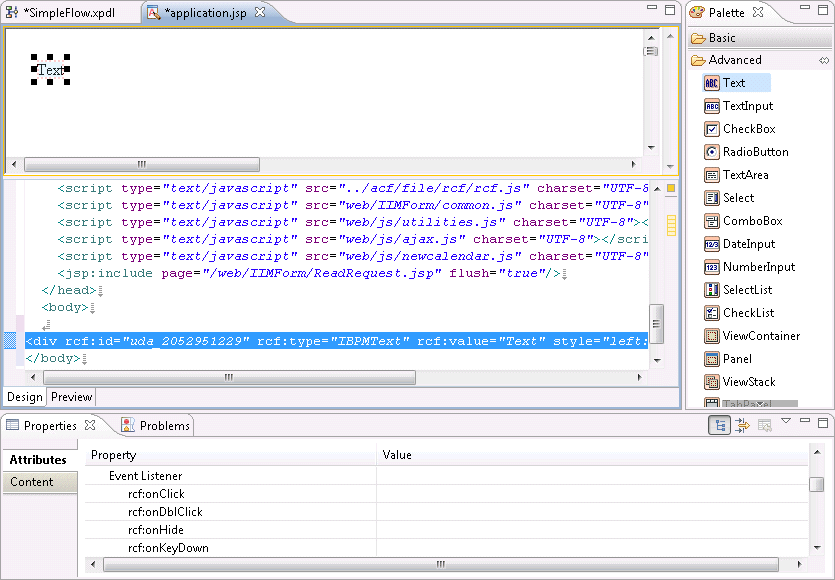
Select the Properties >> Attributes tabs, and enter the name of the label that will be displayed for the input form as the Property >> rcf:value value.
Here, enter "Host Name:" as the label of the input field for the host name that will be passed to the "Stop the server" operation component.
rcf:value: Host Name:
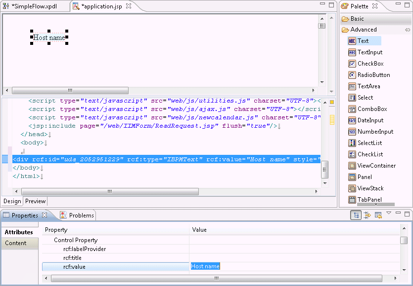
The label for the field that is used to enter the reason for the application is added.
rcf:value: Application reason:
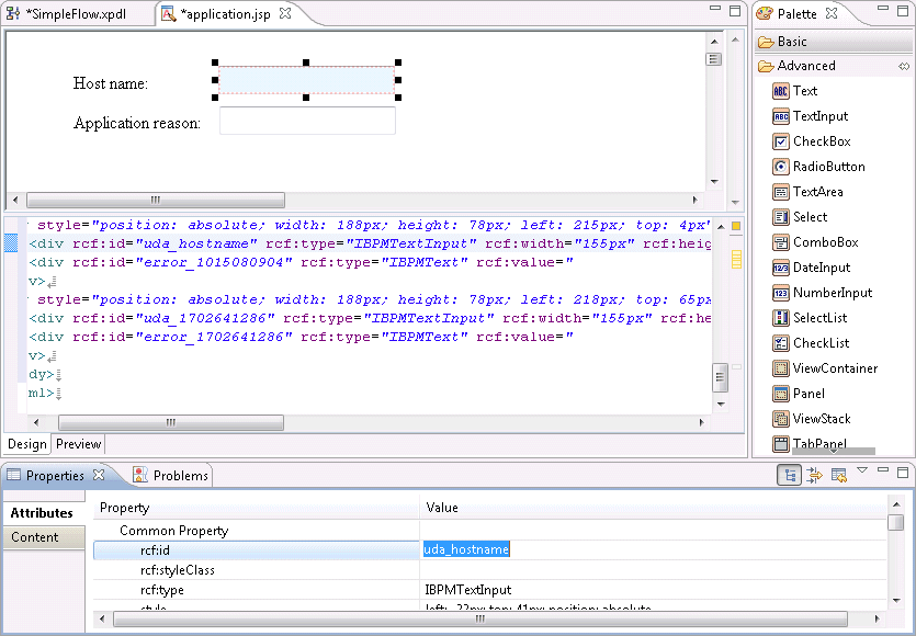
Select the TextInput item in the Palette >> Advanced folder. Click the location where you want to position the item on the Design Editor to add the TextInput item.

Select the Properties >> Attributes tabs, and enter the user defined attribute ID that will be associated with the input field (TextInput) as the Common Property >> rcf:id value.
rcf:id: uda_hostname (The "uda_" part is required)
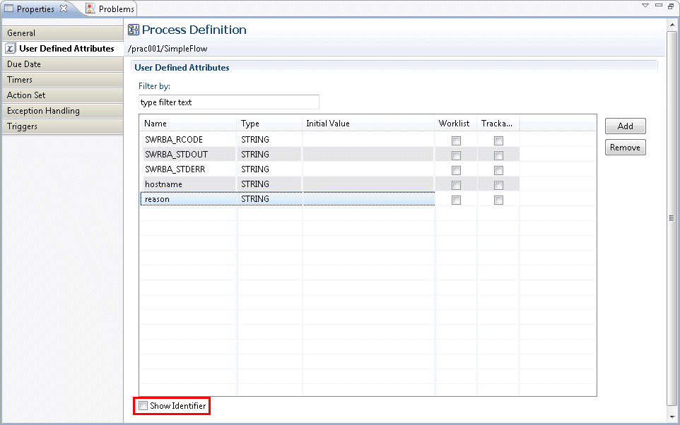
Note that the user defined attribute (UDA) ID can be referenced using the following procedure:
Display the Process Definition Editor.
Select the Properties >> User Defined Attributes tabs.
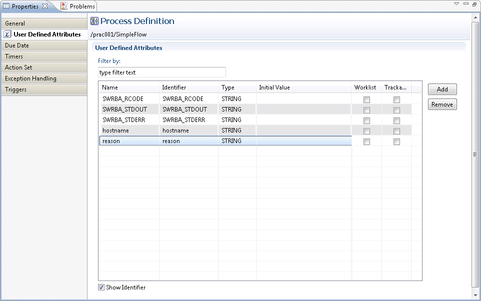
Select the Show Identifier check box.
The ID column is displayed on the right of the Name column, so the user defined attribute IDs can be checked.
In the same way, the field that is used to enter the reason for the application is added.
rcf:id: uda_reason (The "uda_" part is required)
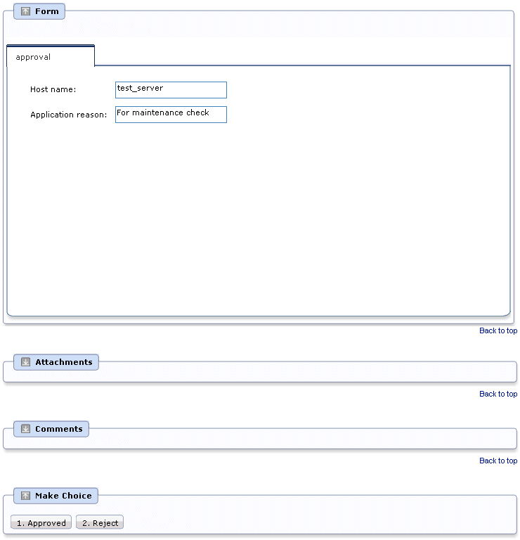
Create the approval form for the activity in the same way as for the application form. Create the approval form based on the application form.
Display on the Web console
The approval form created here will be displayed on the Web console as follows:
Operating procedure
In the Navigator view, select and right-click application.jsp, then select Copy from the pop-up menu.

In the Navigator view, select and right-click the web folder, then select Paste from the pop-up menu.
The Name Conflict dialog box will be displayed.
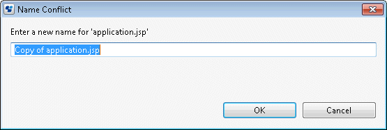
Change the Name Conflict dialog box input field value to approval.jsp, then click the OK button.
approval.jsp is created under the web folder of the Navigator view.
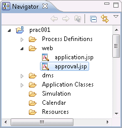
In the Navigator view, select and right-click approval.jsp, then select Open from the pop-up menu.
The QuickForm Design Editor will be displayed.
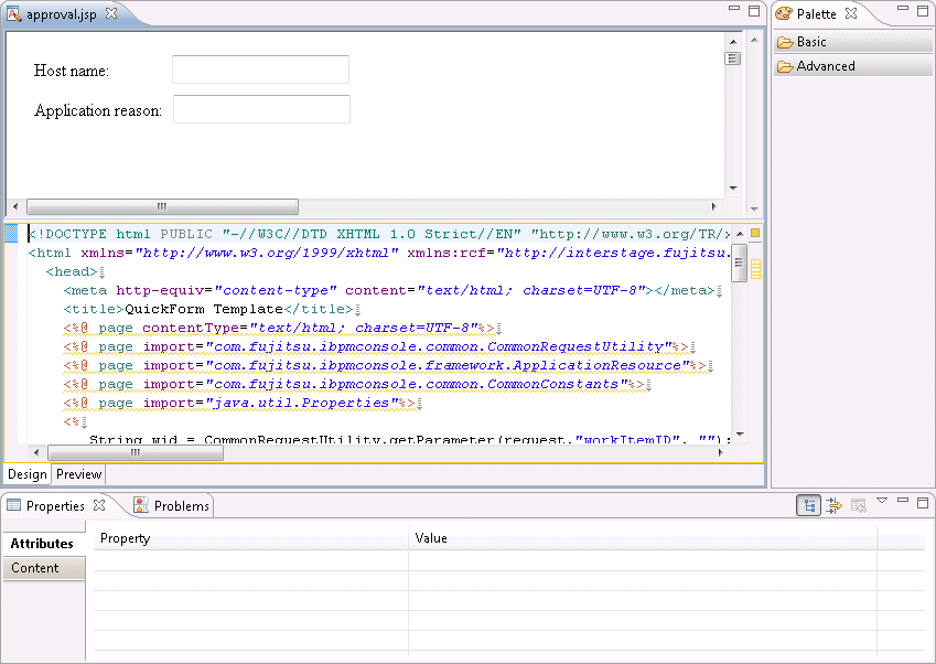
Select the Host Name input field (TextInput).
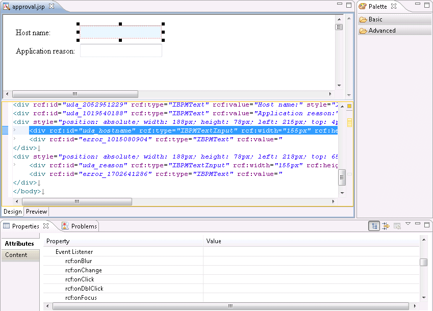
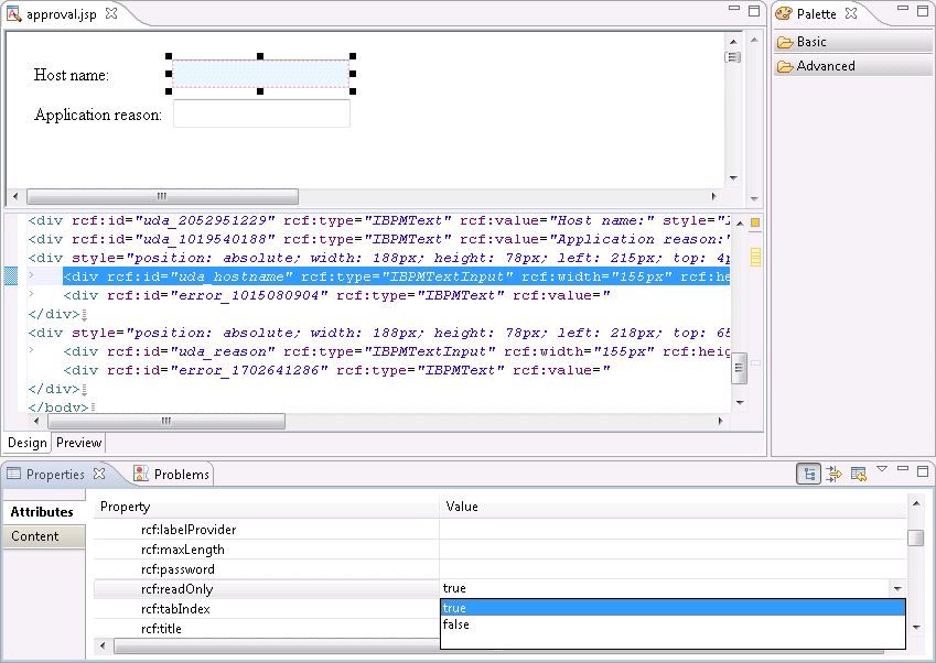
Select the Properties >> Attributes tabs, then specify true as the Property >> rcf:readOnly value. Additionally, specify false as the Property >> rcf:enabled value.
Point
So that the approval form cannot be executed by editing the host name entered in the application form, setting true for the Property >> rcf:readOnly value will change this to a read-only field.
Additionally, by specifying false as the Property >> rcf:enabled value, there will be no focal point.
Select the Application reason input field (TextInput) and, in the same way as for the Host Name input field, specify true as the Property >> rcf:readOnly value. Specify false as the Property>> rcf:enabled value.
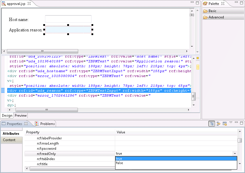
Select File >> Save to save the approval form.
In the Process Definition Editor, right-click the activity then select QuickForm >> Add Node.

Select approval.jsp from the tree in the Add QuickForm reference dialog box, then click the OK button.
The confirmation form (approval.jsp) is set for the activity.
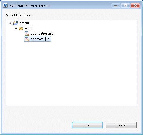
Create the confirmation form for the activity in the same way as for the application/approval form. Create the confirmation form based on the approval form.
Display on the Web console
The confirmation form created here will be displayed on the Web console as follows:
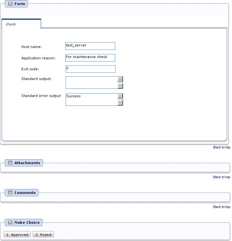
Operating procedure
In the Navigator view, select and right-click approval.jsp, then select Copy from the pop-up menu.
In the Navigator view, select and right-click the web folder, then select Paste from the pop-up menu.
The Name Conflict dialog box will be displayed.
Change the Name Conflict dialog box input field value to check.jsp, then click the OK button.
check.jsp is created under the web folder of the Navigator view.
In the Navigator view, select and right-click check.jsp, then select Open from the pop-up menu.
The QuickForm Design Editor will be displayed.
Select the Text item in the Palette >> Advanced folder. Click the location where you want to position the item on the Design Editor to add the Text item.

Select the Properties >> Attributes tabs, and enter the name of the label that will be displayed for the confirmation form as the Property >> rcf:value value. Here, enter Exit code as the label of the field that will display the "Stop the server" operation component execution results.
rcf:value: Exit code:

Select the TextInput item in the Palette >> Advanced folder. Click the location where you want to position the item on the Design Editor to add the TextInput item.
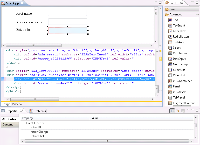
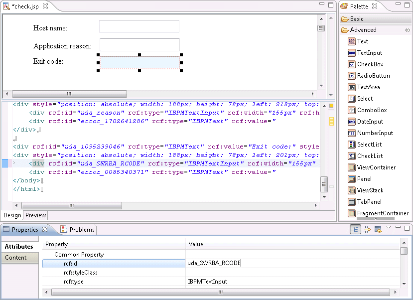
Select the Properties >> Attributes tabs, and enter the user defined attribute ID that will be associated with the input field (TextInput) as the Common Property >> rcf:id value.
rcf:id: uda_SWRBA_RCODE (The "uda_" part is required)
Select the Text item in the Palette >> Advanced folder. Click the location where you want to position the item on the Design Editor to add the Text item.
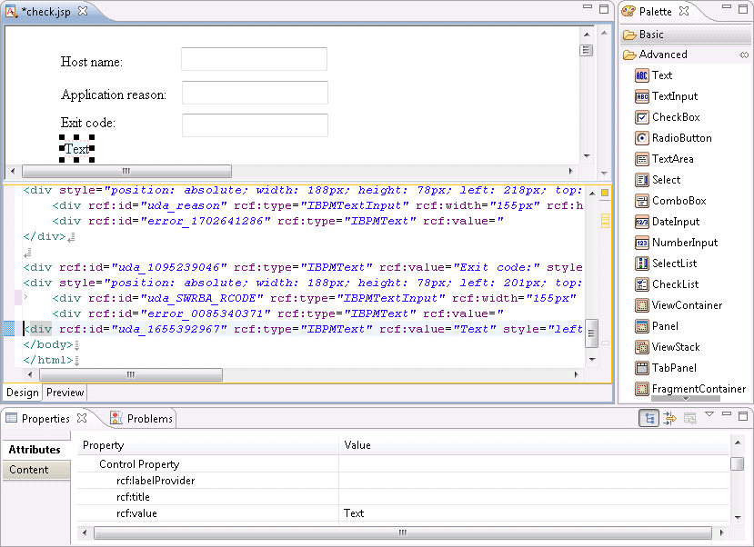
Select the Properties >> Attributes tabs, and enter the name of the label that will be displayed for the confirmation form as the Property >> rcf:value value. Here, enter "Standard output" as the label of the field that will display the "Stop the server" operation component standard output.
rcf:value: Standard output:
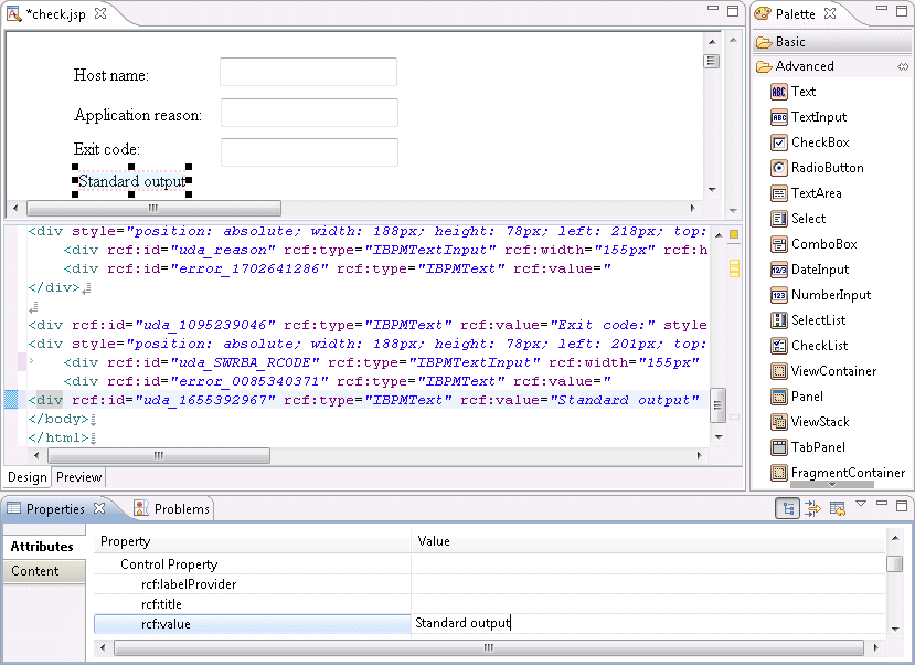
Select the TextArea item in the Palette >> Advanced folder. Click the location where you want to position the item on the Design Editor to add the TextArea item.
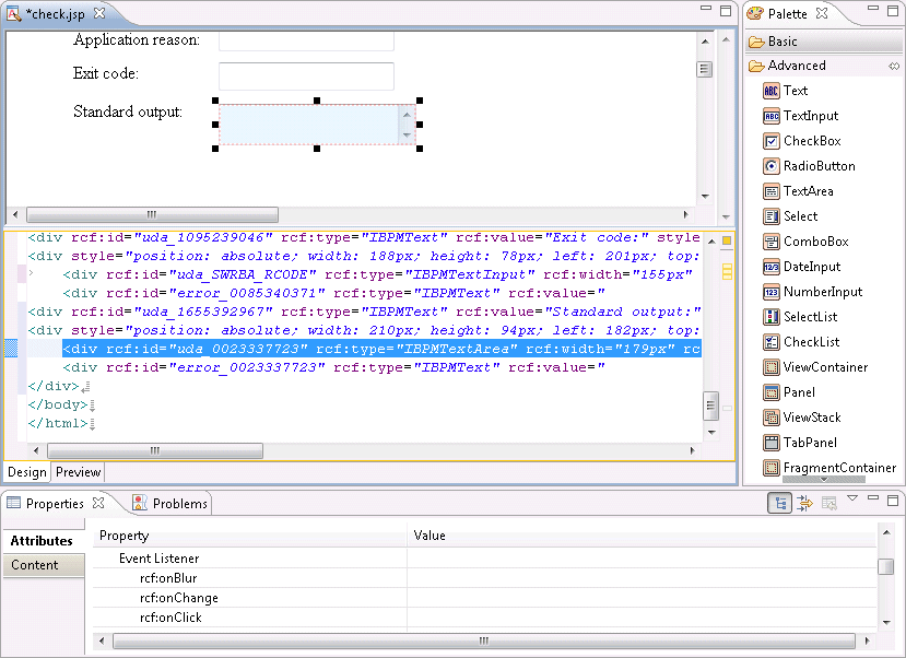
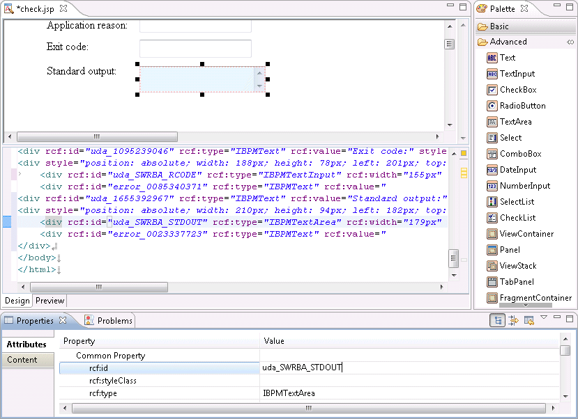
Select the Properties >> Attributes tabs, and enter the user defined attribute ID that will be associated with the input field (TextArea) as the Common Property >> rcf:id value.
rcf:id: uda_SWRBA_STDOUT (The "uda_" part is required)
Information
The number of rows and columns for TextArea items can be specified by specifying values for the rcf:rows and rcf:cols properties under Property.
In the following example, 5 rows x 40 columns are set:

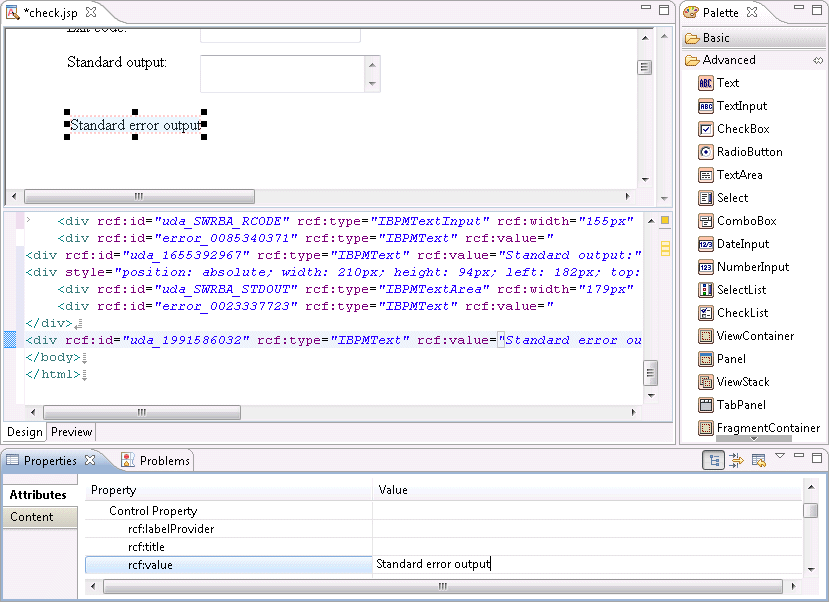
Select the Text item in the Palette >> Advanced folder then place it on the Design Editor. Select the Properties >> Attributes tabs, and enter the name of the label that will be displayed for the confirmation form as the Property >> rcf:value value.
rcf:value: Standard error output
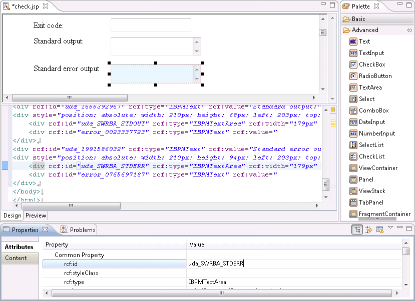
Select the TextArea item in the Palette >> Advanced folder and place it on the Design Editor. Select the Properties >> Attributes tabs, and enter the user defined attribute ID that will be associated with the input field (TextArea) as the Property >> rcf:id value.
rcf:id: uda_SWRBA_STDERR (The "uda_" part is required)
Select File >> Save to save the confirmation form.
In the Process Definition Editor, right-click the activity then select QuickForm >> Add Node.
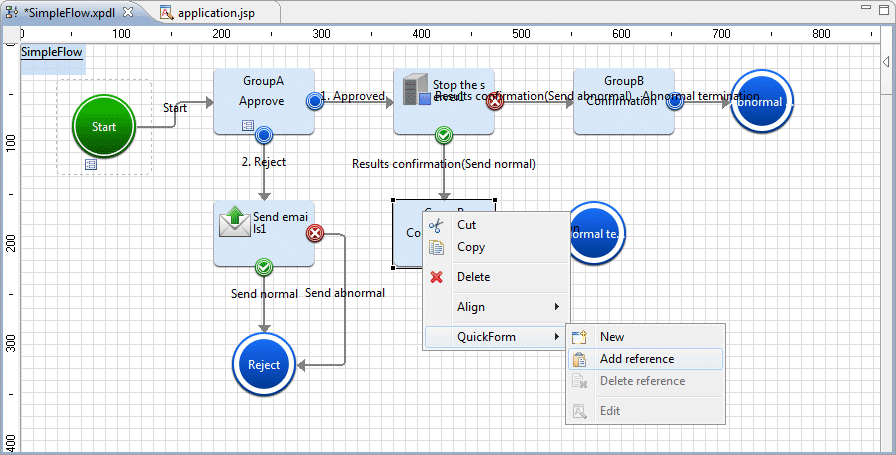
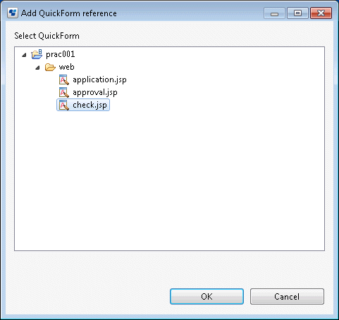
Select check.jsp from the tree in the Add QuickForm reference dialog box, then click the OK button.
The confirmation form (check.jsp) is set for the activity.
This completes the creation of the Automated Operation Process with human tasks included.