Multiple parameters can be passed to operation components as input information for the operation component when the operation component is executed. (The execution results for values stored in the UDA, or for another operation components, are referred to as "variable parameters")
Use of the variable parameter enables the execution results for values stored in multiple variables (UDAs) or other operation components to be passed to the input information (commandline) of the Execute arbitrary command operation component node, for example.
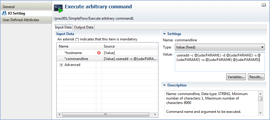
Variable parameters can be used for operation component nodes that have "fixed" as the input information type, and do not have the PASSWORD data type.
About variable parameter
Format | Description |
|---|---|
@{uda:name} | The value held by the user-defined attribute (UDA) specified in <name> is passed as input information to the operation component node. |
@{:node name:execution results} | The value for the execution results specified in <execution results> that is specified in <node name> is passed as input information to the operation component node. <node name> represents the name that was entered in the Name field of the General tab. <execution results> represents the name that can be selected from the Execution results combo-box of Settings after clicking the IO Setting >> Output Data tabs. |
The variable parameters are interpreted based on the following rules:
Items specified as @{uda: <name>} or @{:<node name>:<execution results>} are replaced with the variable parameter values.
Consecutive @ characters are replaced with a single one.
The rules above are applied in the order in which they are described.
Variable parameter input compensation
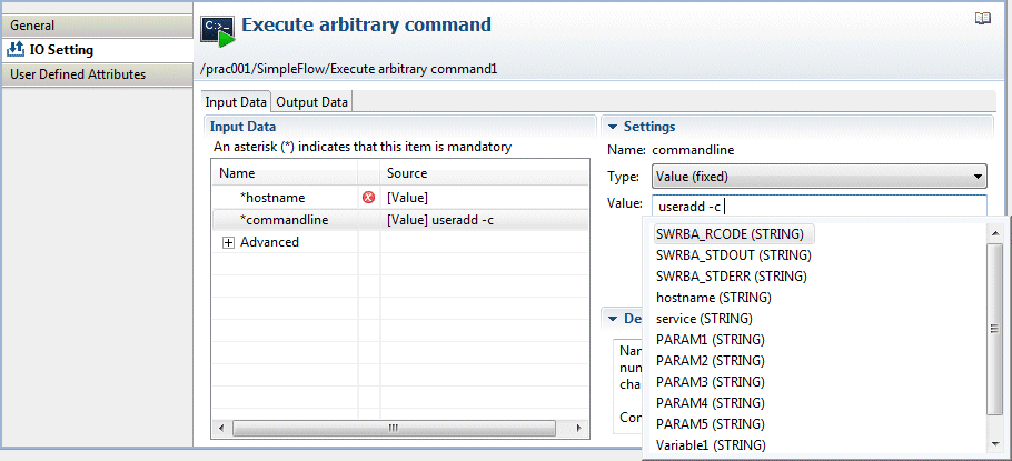
By pressing the "Ctrl+Space" key in the Value field, it is possible to define the variable parameter easily. When the "Ctrl+Space" key is pressed, the list of UDAs will be displayed. When the UDA is selected from the list, it will be converted to "@{uda:UDA name}" notation and inserted in the Value field.
Note
When the Value field on the Studio contains a parameter format, the format is replaced with a blank character and its length is checked. When the operation component is executed, replace the variable parameter format with the actual value, and then verify whether this is within the maximum number of characters. In this case, if the result of the replacement of the variable parameter format with the actual value is a result that exceeds the maximum number of characters, an error will occur when the operation component is executed.
This section describes how to pass parameters to the command line of an "Execute an arbitrary command" operation component node.
Select the "Execute an arbitrary command" operation component node in the Process Definition Editor.

From the Input Data section list, select "commandline".
The windowSettings Section) for setting the input information ("commandline") is shown on the right.
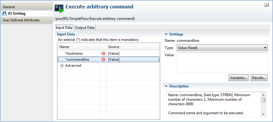
From the Settings >> Type combo-box, select Value (fixed).
In the Settings >> Value field, define the input information that you want to be passed as "commandline". By defining the input information in the format "@{uda:<name>}", it can be replaced with the value stored in the variable (UDA) shown as <name> when the operation component is executed. Additionally, by defining content in the format "@{:<node name>:<execution results>}", when the operation component is executed it can be replaced by the <execution results> value for the operation component shown in <node name>.
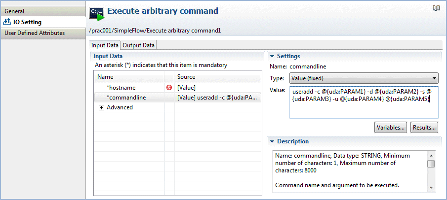
Example of value settings:
useradd -c @{uda:PARAM1} -d @{uda:PARAM2} -s @{uda:PARAM3} -u @{uda:PARAM4} @{uda:PARAM5}
Assuming the UDA values during operation activity execution are as below:
PARAM1 | "Taro Fujitsu" |
PARAM2 | /home/t-fujitsu |
PARAM3 | /bin/sh |
PARAM4 | 30000 |
PARAM5 | t-fujitsu |
commandline is replaced as follows, and passed as the operation component input information:
useradd -c "Taro Fujitsu" -d /home/t-fujitsu -s /bin/sh -u 30000 t-fujitsu |
Information
The variable parameter can be specified in the Browse variables dialog box, which is displayed by clicking the Browse variables button. When the variable is selected in the Browse variables dialog box and the OK button is clicked, "@{uda:<name>}" will be inserted in the cursor location of the Value field.
The variable parameter can be specified in the Browse execution results dialog box, which is displayed by clicking the Browse execution results button. When the node name and execution results are selected in the Browse execution results dialog box and the OK button is clicked, "@{:<node name>:<execution results>}" will be inserted in the cursor location of the Value field.
Note
Parameters containing space characters must be enclosed by quotes (as is the case with PARAM1 in the example above), otherwise the space character will be identified as a parameter delimiter.
Filter the operation component output (execution result, standard output, or standard error output) and pass it to the next operation component.
To filter the output, define the filter process with JavaScript.
Extract node values specified with XPath from the operation component output information (XML format) and use them as input to the succeeding operation component.
Refer to "Obtain configuration information" in "Reference for Operation Components" in the Systemwalker Runbook Automation Reference Guide for information on the operation component output information (XML format).
In the Process Definition Editor, select the operation component node.
The operation component node that is selected here will output the XML format information as standard output.
Select the Properties >> IO Setting >> Output Data tabs.
Click the Add button.
The new output data is added to the Output Data list.
From the Output Data list, select the new output data that was added.
The settings window will be displayed on the right.
From the Settings >> Execution Result combo-box, select "ci_get_result".
From the Settings >> Variable list, select the variable (UDA) that will store the filtered result. Here, "hostname" has been selected.
Click the Settings >> Define Filter >> Add button.
The Filter settings dialog box will be displayed.
From the List of filters list, select the Extract XML attribute filter, then click the Add >> button.
The filter is added to the Filter to be applied list, and the content set for the filter is displayed in the Define Filter field.
Enter the XPath expression in the XPath field.
Here, the following XPath expression is entered:
/entities/item/record/LogicalServer
Enter the name of the attribute that is to be extracted in the Attribute name field.
Here, the following name is entered:
hostname
Select the Test tab, and enter the test data in the Input field.
Here, the following data is entered as test data:
<?xml version="1.0" encoding="UTF-8"?> |
Click the Run test button.
The filter test results will be displayed in the Result field. In this example, the following results are obtained:
server-A |
Click the OK button to complete the filter settings.
Lines containing a specific keyword can be extracted from the operation component output.
In the example shown below, the command that is executed using the Execute arbitrary command component extracts specific rows containing keywords from the results that are output to the standard output.
In the Process Definition Editor, select the operation component node.
Select the Properties >> IO Setting >> Output Data tabs.
Click the Add button.
The new output data is added to the Output Data list.
From the Output Data list, select the new output data that was added.
The settings window will be displayed on the right.
From the Settings >> Execution Result combo-box, select "command_stdout".
From the Settings >> Variable list, select the name of the variable (UDA) that will store the processed result. Here, "ipaddress" has been selected.
Click the Settings >> Define Filter >> Add button.
The Filter settings dialog box will be displayed.
From the List of filters list, select the Extract lines filter, then click the Add >> button.
The filter is added to the Filter to be applied list, and the content set for the filter is displayed in the Define Filter field.
From the Line extraction method combo-box, select All lines containing the target string.
In the Target string field, enter "IP Address".
Select the Test tab, and enter the test data in the Input field.
In this example, the following data is specified as the test data:
Ethernet adapter1:
        IP Address. . . . . . . . . . . . : 192.168.238.1
        Subnet Mask . . . . . . . . . . . : 192.0.2.0
        Default Gateway . . . . . . . . . :

Ethernet adapter2:
        IP Address. . . . . . . . . . . . : 192.168.187.102
        Subnet Mask . . . . . . . . . . . : 192.0.2.0
        Default Gateway . . . . . . . . . : 192.168.187.1
Click the Run test button.
The filter test results will be displayed in the Result field. In this example, the following results are obtained:
        IP Address. . . . . . . . . . . . : 192.168.238.1[Line feed]
        IP Address. . . . . . . . . . . . : 192.168.187.102[Line feed]
Click the OK button to complete the filter settings.
One automated operation process can be created by connecting multiple automated operation processes, as shown below.
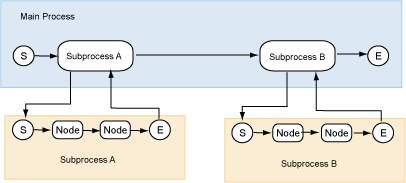
The procedure where an automated operation process with human intervention and an automated operation process without human intervention are connected using a main automated operation process to form a single automated operation process is shown below.
The explanation here assumes that the automated operation processes (called sub automated operation processes) that will be connected have already been created in the application project.
Note
Automated operation processes cannot be connected across different application projects.
(1) Create the main automated operation process
Select New >> Process Definition from the Files menu.
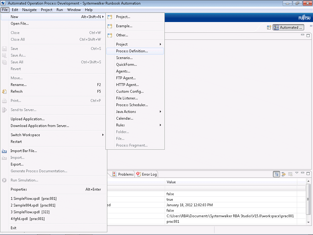
Click Browse in the New Process Definition window. Select the project that was created earlier, then click the OK button.
Enter a name for the automated operation process in the Name field, and a description in the Description field. The name of the main automated operation process in this example will be "MainWorkflow".
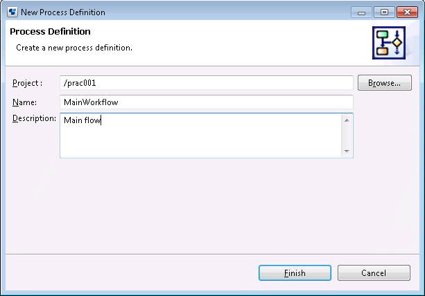
Click the Finish button.
The automated operation process that has just been created will be displayed in the Navigator view. When the Process Definition Editor is opened, a "Start" Node will be added automatically.
(2) Position the Subprocess Node
Click the Subprocess in the Basic tab in Palette.

With the Process Definition Editor, add the Subprocess Node by pointing and clicking the area where it should be placed. If necessary, change the name and add an explanation.

Set the transition route of the activity. Set the route by connecting activities with arrows.
Select the Subprocess Node using the mouse.

Click the Properties >> Data Mapping tabs and click the Browse button in the Sub Process Definition field.
The Select Subprocess Definition dialog box will open.

Click the Get List button.
A list of process definitions that can be selected will be displayed in the Process Definition Name list.
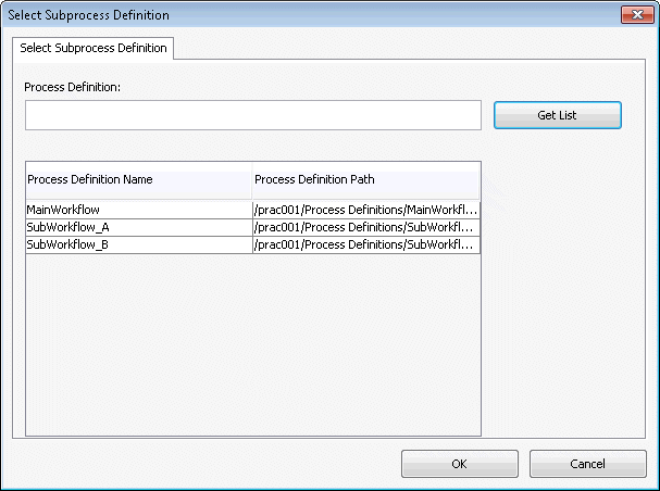
Select the process definition that will be executed as the subprocess from the list, then click the OK button. "SubWorkflow_A" is selected as the subprocess definition in this example.
The name of the subprocess definition that was selected in the Sub Process Definition field will be displayed.
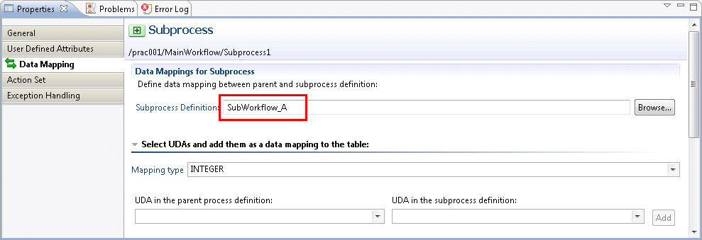
In the same way, place and configure the settings for the Subprocess Node for sub automated operation process B.
(3) Adding Exit Nodes
Add an Exit Node to the end of the automated operation process.
Add the Exit Node to the Process Definition Editor by clicking the Exit in the Basic tab in Palette.
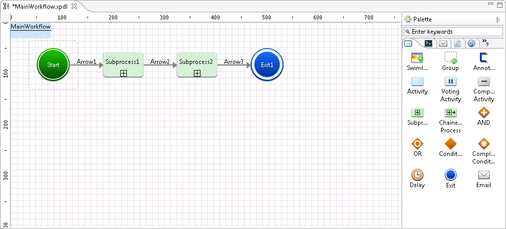
This completes the procedure for creating an automated operation process.
The procedure that is used to create an automated operation process that will be started automatically according to an event that has occurred externally is shown below.
Here, the automated operation process will start when the XML data /RBAEvent/ID element value sent when an event occurs externally is "msg0001".
Note that the XML data is sent when the event notification command is executed using the event monitoring software.
Refer to the following XML schema for information on the format of the XML data that is sent.
<?xml version="1.0" encoding="UTF-8"?> <xsd:schema xmlns:xsd=http://www.w3.org/2001/XMLSchema targetNamespace=http://www.fujitsu.com/2007/systemwalker/itpm xmlns:itpm=http://www.fujitsu.com/2007/systemwalker/itpm attributeFormDefault="unqualified" elementFormDefault="qualified"> <xsd:element name="RBAEvent"> <xsd:sequence> <xsd:element name="msgID" type="xsd:string" /> <xsd:element name="HostName" type="xsd:string" /> <xsd:element name="MessageKey" type="xsd:string" /> <xsd:element name="ApplicationName" type="xsd:string" /> <xsd:element name="Comment" type="xsd:string" /> </xsd:sequence> </xsd:element> </xsd:schema> |
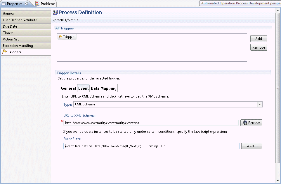
In the Process Definition Editor, click the Properties >> Triggers tabs.

Click the Add button.
In the Trigger Details section, click the General tab, then select theEnable check box.

In the Trigger Details section, click the Event tab, then configure the following settings:
Type: XML schema
XML schema URL: http://[IP address or host name of the Management Server]:[Port number of the Management Server (Web server)/notifyevent/notifyevent.xsd

Click the Retrieve button.
Click the A+B... button to set the Event Filter (the startup condition for the automated operation process). The Expression Builder dialog box will be displayed.
From the Functions combo box, select "eventData.getXMLData" then click the Add button. The JSFunction Editor dialog box will be displayed.
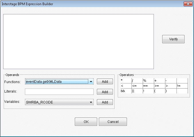
In the XPATH field, enter the following XPath then click the OK button.
XPATH: "/RBAEvent/ID/text()"

FromOperator, click the comparison operator that will evaluate the condition. (Here, "==" has been specified)
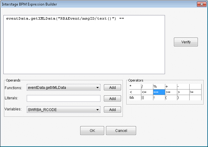
In the Literals field, enter the condition then click the Add button. (Here, "msg0001" has been specified)
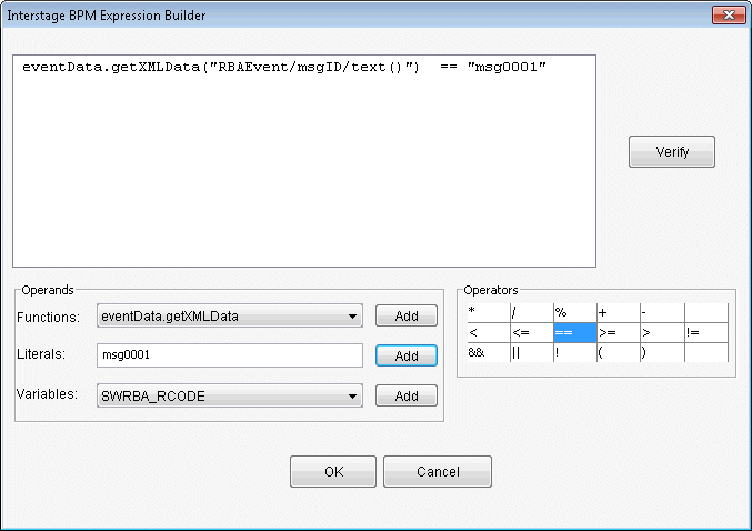
Click the Verify button to verify the expression content.
Click the OK button.
Click the OK button in the Expression Builder dialog box.
The content for the event filter that was created in the Event Filter field will be displayed.
Point
Specify the Automated Operation Process definition start conditions in the event filter.
The following items that are sent from the event notification command can be used as start conditions:
Message ID
Host name
Comment
The evaluation results of these item values can be used as start conditions.
If the following types of events are discovered, transition of the Activity Nodes in the Automated Operation Process can occur by linking the monitoring software and the event notification command:
Errors that have occurred on the Business Server
Exceeding of thresholds for performance monitoring items
It is also possible to change the node transition destination automatically using the variable information contained in the event notification command.
The figure below shows the relationship between the event notification command and the monitoring software.
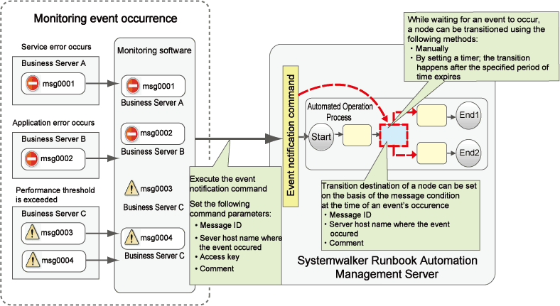
Note that automatic transition as a result of an event can only occur for the Activity Node.
Additionally, separate software for the monitoring of events is also required.
The procedures for node transition using the event notification command and the creation of the Automated Operation Process, for which the node transition destination changes as a result of an event, are explained in this section.
The procedure for node transition using the event notification command is explained in this section.
Note that, if this type of event occurs, configure the monitoring software settings so that the event notification command is executed on the Management Server using that monitoring software.
(1) Create the event filter
In the Process Definition Editor, create the process definition and select the automatic transition target Activity Node.

Click Properties >> Triggers.

Click the Add button.
In the All Triggers section, click the General tab and select the Enable check box.
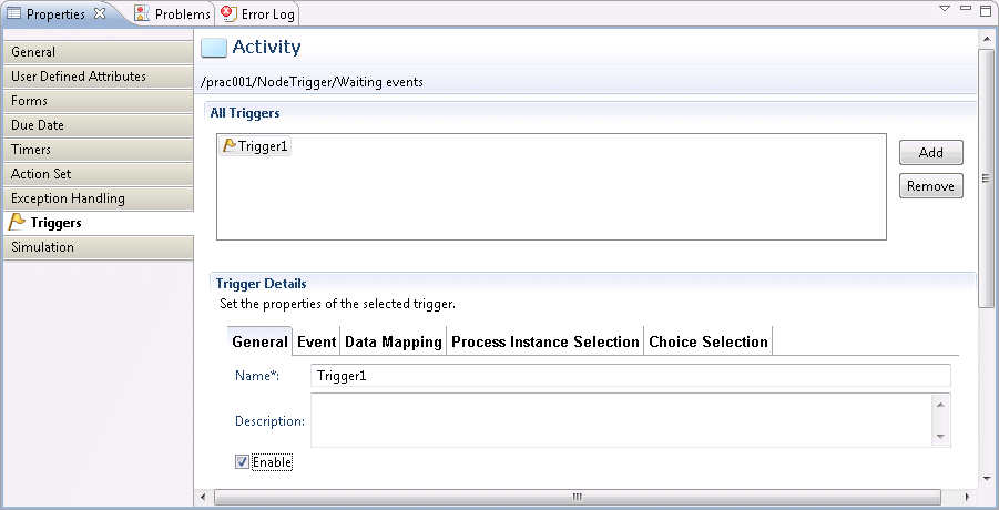
Click the Event tab, and configure the following settings:
Type: XML schema
XML schema URL: http://[IP address or host name of the Management Server]:[Port number of the Management Server (Web server)]/notifyevent/notifyevent.xsd
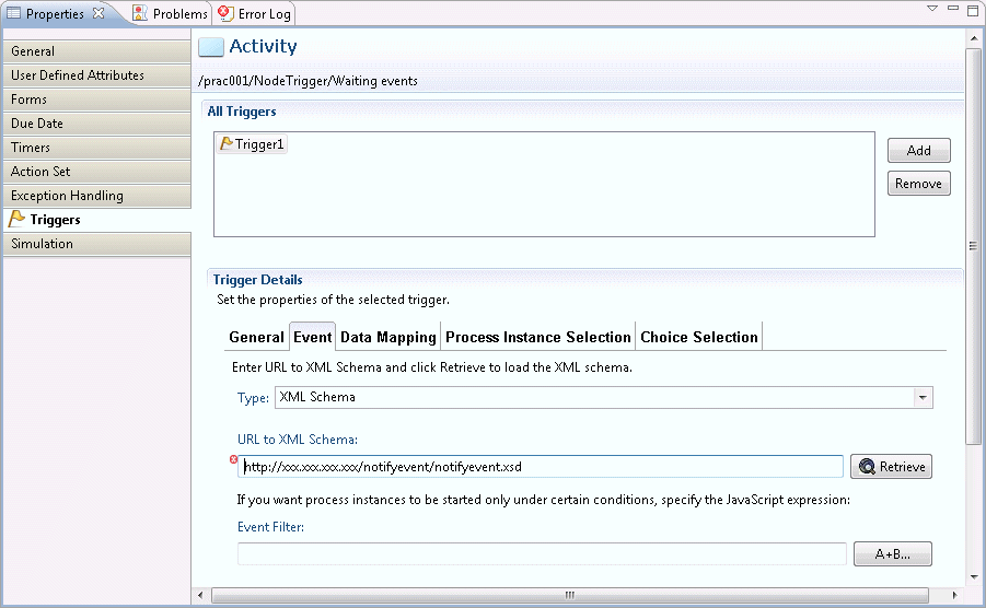
Click the Retrieve button.
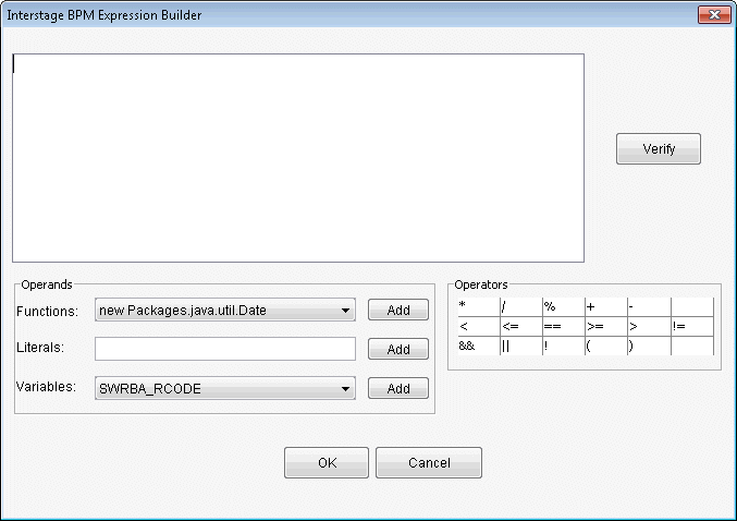
Click the A+B button to set the Activity Node transition condition for the Event Filter.
The Expression Builder dialog box will be displayed.
From the Functions combo-box, select eventData.getXMLData and click the Add button.
The Interstage BPM Expression Builder dialog box will be displayed.
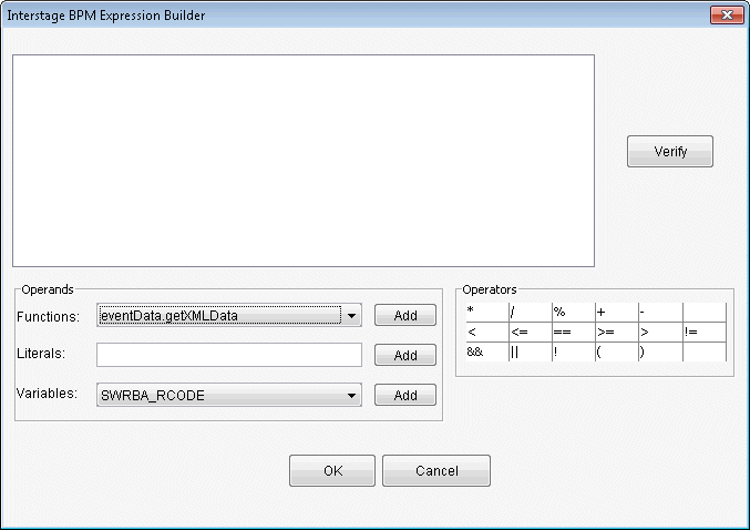
In the XPATH field, type the following XPath and click the OK button.
XPATH: "RBAEvent/msgID/text()"
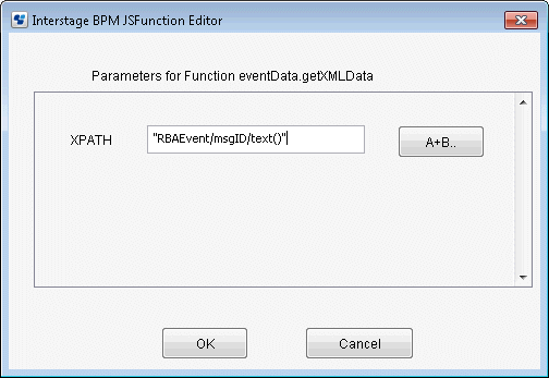
From Operators, click the inequality sign that will evaluate the condition. (Here, "==" has been specified.)
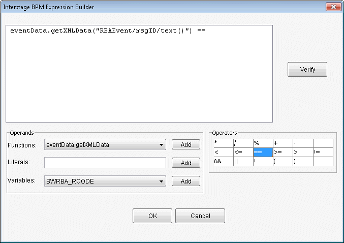
In the Literals field, type the condition and click the Add button. (Here, "msg0001" has been specified.)
If the following characters are used in the condition, use the \" escape sequence.
\, ", '
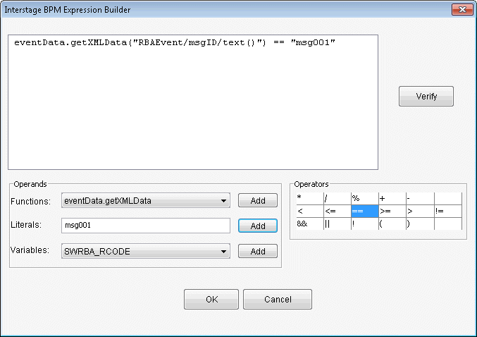
Add operator to the expression that was created, and click the "||" operator that will evaluate the condition from Operators.
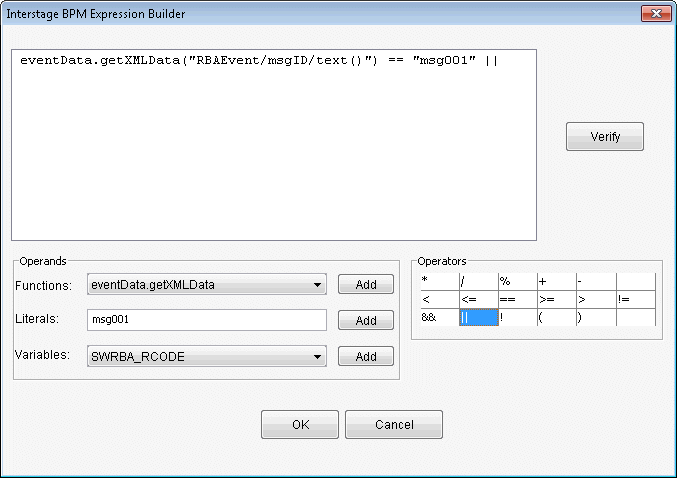
Using the same procedure as for the msg0001 expression, add the msg0002 condition expression.
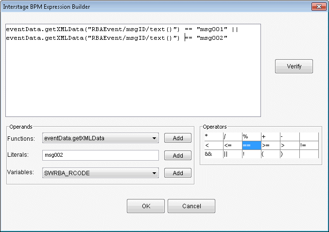
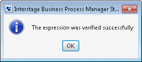
Click the Verify button to verify the expression.
Click the OK button.
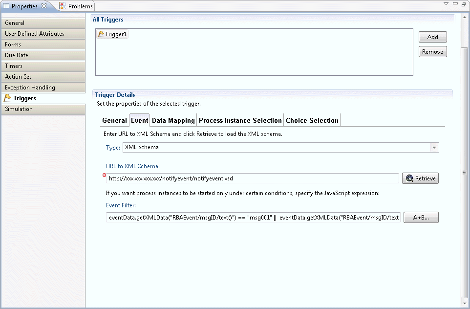
Click the OK button in the Expression Builder dialog box.
The content for the event filter that was created in the Event Filter field will be displayed.
Point
Specify the Automated Operation Process definition start conditions in the event filter.
The following items that are passed from the event notification command can be used as start conditions:
Message ID
Host name
Comment
The evaluation results of these item values can be used as start conditions.
(2) Node transition
From the Automated Operation Process Group list displayed in System Administration >> Process Group Settings of the Web console, select the Automated Operation Process Group containing the Automated Operation Process to transit.

Click Access Key in the Details tab of the Automated Operation Process group and obtain the access key.
The access key is information that identifies the Automated Operation Process that is to be started from an event.

Point
The expiry for the access key is one year from the day on which the process group was registered in the Management Server.
When the access key expires, a user with administrator privileges should obtain a new access key from the Web console.
Configure the message ID, host name, and access key as the event notification command parameters so that the event notification command is executed on the Management Server, using the monitoring software, when the monitored event occurs.
Example: If the message ID for the event that occurred is "msg0001" and the host name of the server on which the event occurred is "test":
swrba_notifyevent -msgID msg0001 -host test -comment "database error" -key "**BEGIN_KEY--{{ezsGjLOinOSbrr7HJD65ksBT2o7X2vXhCp7f2iqAqhnboFDFj5le+Y6A1c/YBUaSo6M/IXYNdHA5 N4Pvd6NI69OYtwt9XrefsuB7y1GpjGqbzssIr0SNNjn6x5q5oCsDdrkjVKTxh4Dj/+16z2yX/w==}}--END_KEY**" |
Refer to "swrba_notifyevent (Event Notification Command)" in the Systemwalker Runbook Automation Reference Guide for information on the event notification command.
Start the process instance, then advance the process instance as far as the node on which the event filter is set.
Node transitions will take place when the event notification command is issued.

Refer to "7.8 Checking Automated Operation Processes" for information on how to check the results of the node transition.
The configuration procedure used so that the transition destination changes according to the message ID value when the message ID for the event that occurred is "msg0001" or "msg0002" is explained in this section.
Node transition is performed by the execution of the event notification command when an event occurs.
The following information can be passed as arguments to the event notification command, and this information can be used in the Automated Operation Process:
Argument name | Meaning | XPath (Note 1) |
|---|---|---|
msgID | Message ID for the event that occurred | "RBAEvent/msgID/text()" |
HostName | Name of the host on which the event occurred | "RBAEvent/HostName/text()" |
Comment | Comment | "RBAEvent/Comment/text()" |
Note 1: XPath is the format defined in the process definition for when the information specified in the event notification command is referenced.
Click the Triggers tab on the Activity Node on which the event filter is set, then select the Choice Selection tab of the Trigger Details section.
The list of arrows that are added to the Activity Node are displayed.

To set the transition destination selection condition JavaScript expression (condition expression), select the arrow from the list of arrows, then click the A+B button.
The Expression Builder dialog box will be displayed.
Here, the condition expression is created so that transition occurs to "msg0001" when the Activity Node arrow is "msg0001" and the message ID value when the message ID for the event that occurred is "msg0001".
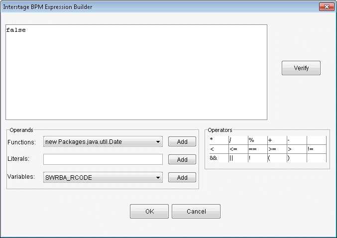
In the Interstage BPM Expression Builder window, create the condition expression using the same procedure as for the creation of the event filter expression.
Note that if a conditional expression has already been set, the conditional expression should be deleted before creating a new one.
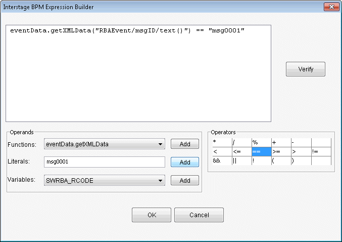
Click the OK button in the Expression Builder window.
The content for the condition expression that was created in the JavaScript Expression field will be displayed.
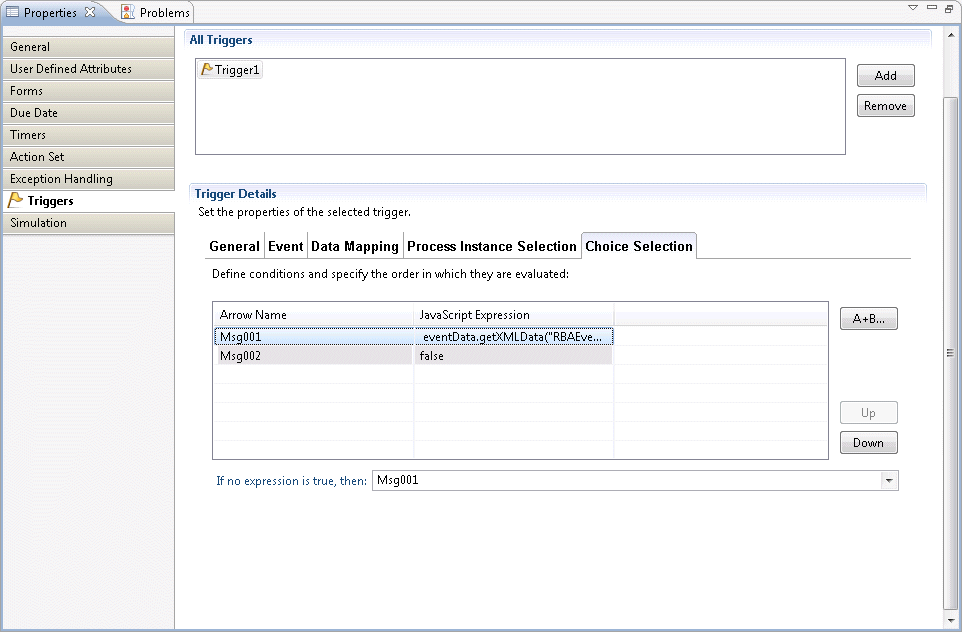
Using the same procedure, create the condition expression for arrow "msg0002".
In this example, the condition expression is created so that transition occurs to "msg0002" when the Activity Node arrow is "msg0002" and the value for the RBAEvent/msgID element of the XML data sent when the event was monitored is "msg0002".
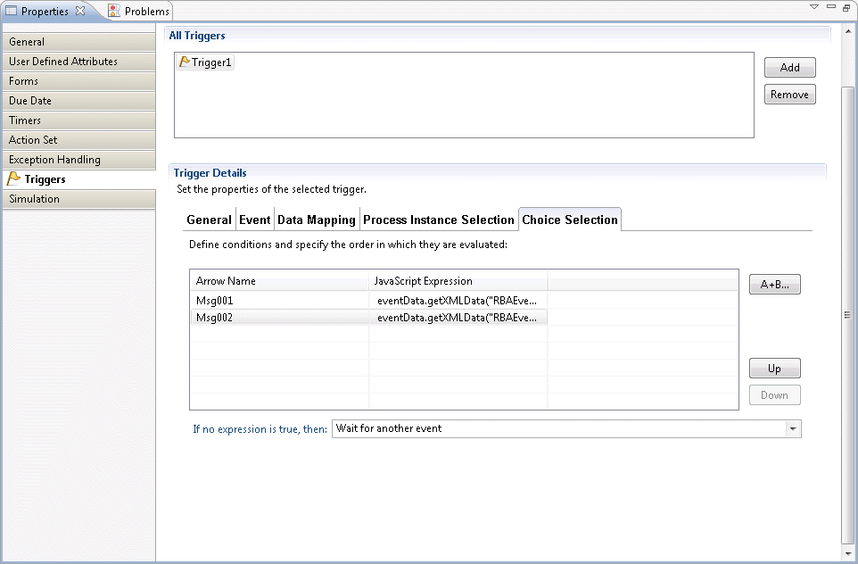
In the If no expression is true,then field of the Trigger Details section, the behavior that will apply can be selected for when an event occurs that does not match the condition expression. The items that can be selected are as follows:
Arrow Name: Node transition occurs for the specified arrow
Wait for another event: Node transition does not occur for any arrows
Items passed using the event notification command can be mapped to the UDA.
By mapping them to the UDA, items can also be used as operation component input values.
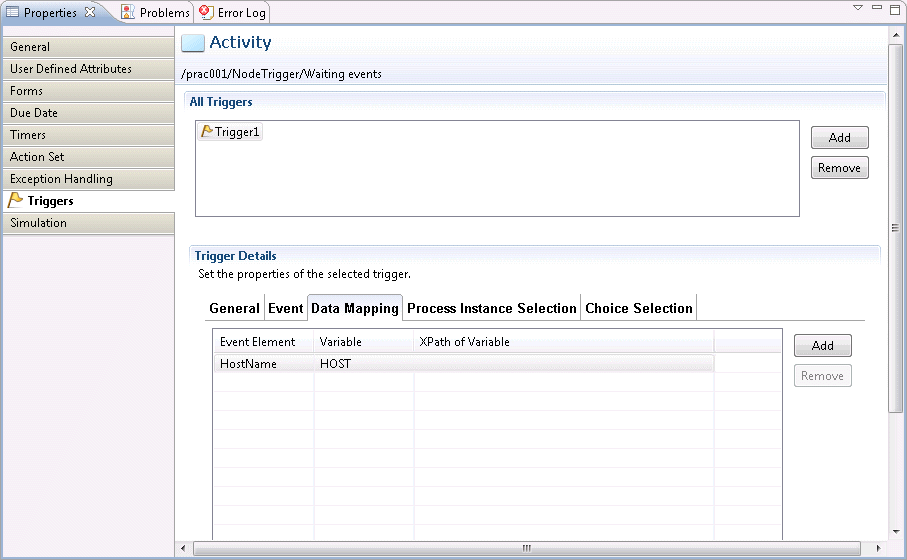
Select the Triggers tab on the activity on which the event filter is set, then select the Data Mapping tab of the section.
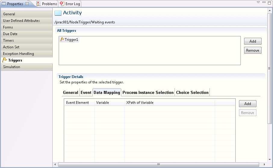
Click the Add button, and select the items shown below from the drop-down list:
Here, the host name is mapped as UDA name: HOST.
Event element: The various RBAEvent element items of the XML data sent when an event occurs can be selected:
HostName: Host name
msgID: Message ID
comment: Comment
Variable: UDA name
The procedure that is used to create the automated operation process that will execute the command after the automated operation process has started and is delayed for the time that was set is shown below.
Click the Delay in the Event folder under the Basic tab of the Palette.
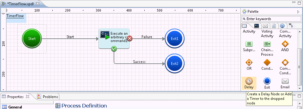
On the Process Definition Editor, add the Delay Node by pointing and clicking the area where it should be placed.

Each node is joined by an arrow. Set an arrow name if necessary.

Select the Delay Node that was placed on the Process Definition Editor and click the Properties >> Timers tabs.
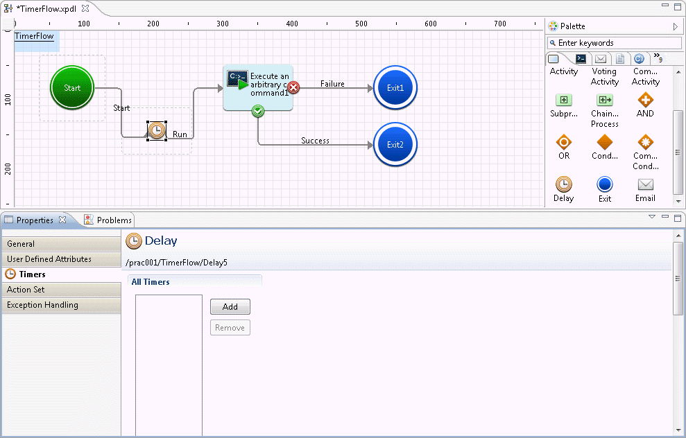
Click the Add button.
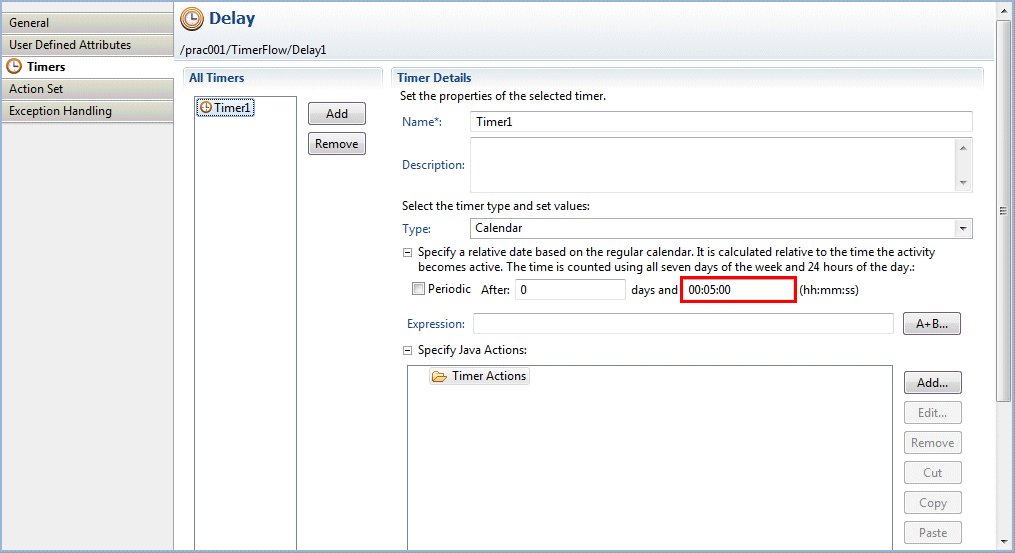
The Timer Details window will be displayed.
Change the timer name if necessary, then set the waiting time.
Here, the delay has been set as a period of 5 minutes. Refer to "Defining Timers" in the "Systemwalker Runbook Automation Studio User's Guide" for information on how to set the delay time.
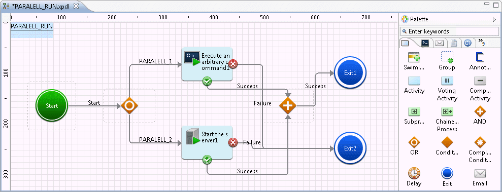
Multiple operation components can be executed in parallel within a single Automated Operation Process.
The procedure for creating an Automated Operation Process that is to execute two operation components in parallel is explained below.
Note
In parallel execution of operation components, OR nodes and AND nodes must be used. Parallel execution that does not use OR nodes and AND nodes cannot be guaranteed.
The running time of each operation component will vary according to the contents of the tasks to be implemented, so the order of parallel execution cannot be guaranteed.
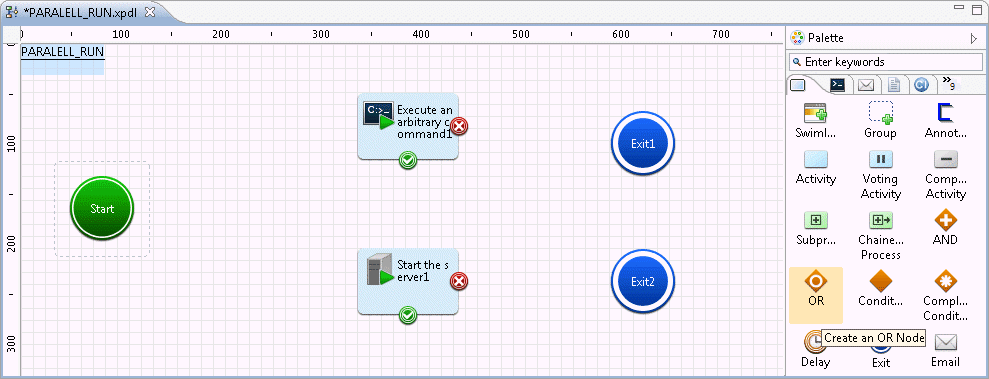
In the Process Definition Editor, position the operation component nodes that are to execute in parallel, and click the OR in the Route folder under the Basic tab of the Palette.
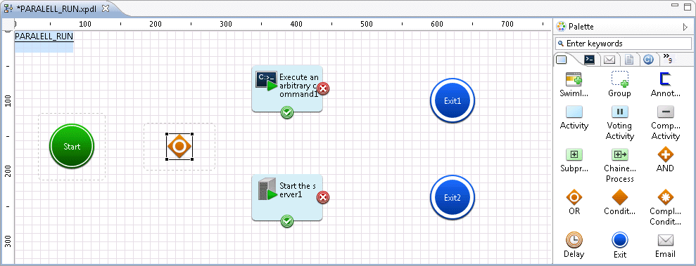
In the Process Definition Editor, move the cursor to the location where you want to place the OR node and click to add the OR node. Ensure that the OR node is positioned before the operation component nodes that are to execute in parallel.
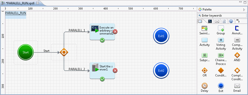
Use arrows to connect the nodes. Set names for the arrows as required. Connect the arrows to all operation component nodes from the OR node.
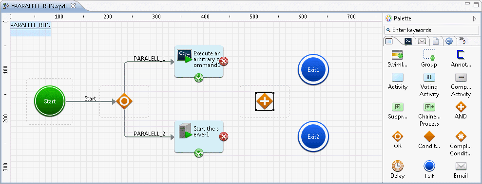
Click the AND in the Route folder under the Basic tab of the Palette, and then, move the cursor to the location where you want to place the AND node. Add the AND node, ensuring that it is positioned after the operation component nodes that are to execute in parallel.
Use arrows to connect the nodes. Set names for the arrows as required. Connect the arrows to the AND node from all operation component nodes that are to execute in parallel.
In an Automated Operation Process, email can be sent using specified date or any time intervals.
As a result, in a case where processing in an Automated Operation Process is suspended due to an approval activity, task reminder email can be periodically posted to the approver.
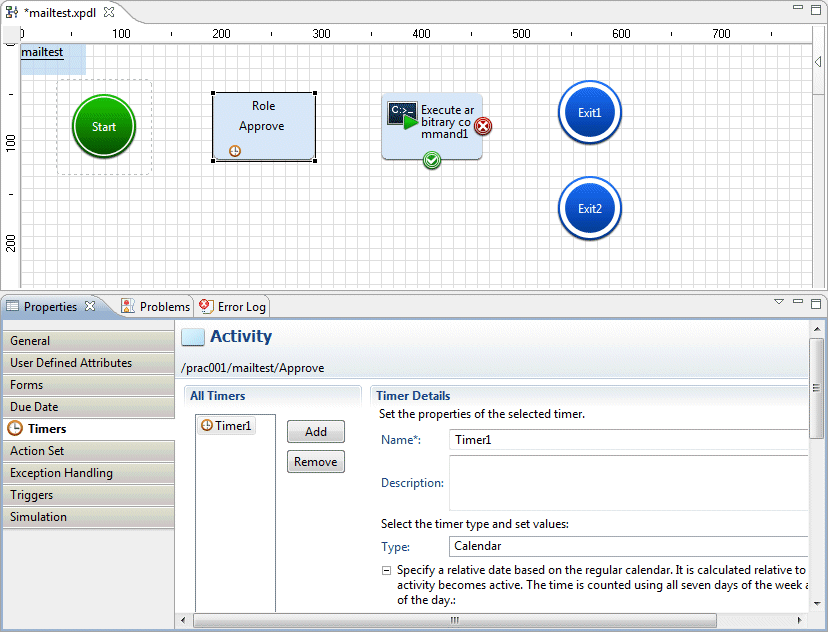
The email send setting can be set in every activity in an Automated Operation Process.
Create an Automated Operation Process and select an activity to be targeted for this setting.
Select the Timers tab from the Properties view and then click the Add button.
You can change the name of the added timer at your discretion.
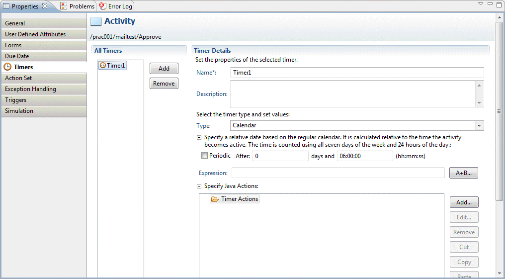
Set a time interval at which email is to be sent. Select the Periodic checkbox and then set the items shown below. Refer to Timer Definitions in the Systemwalker Runbook Automation Studio User's Guide for details of each item.
Item | Description |
|---|---|
Type | Select a timer type from any of the following:
|
Day | Set an interval in number of days. Combining this with the time setting allows a regular interval to be specified. When you select the Periodic checkbox, After days changes to Every days. |
Time | Set a time interval. Combining this with the Day setting allows a regular interval to be specified. |
For example, if 0 (every day) is set in day and 03:00:00 is set in time, email will be posted every three hours every day from when the setted activety was started.

In addition, if 1 (every day) is set in day and 06:00:00 is set in time, email will be posted every one day and six hours(30 hours) from when the setted activety was started.

Information
If the email notification setting has been enabled, the first email notification will be implemented immediately after processing transitions to the relevant activity.
Below is an input example in which a calendar is selected for the timer Type and 1 (every day) is set in day and 06:00:00 is set intime.
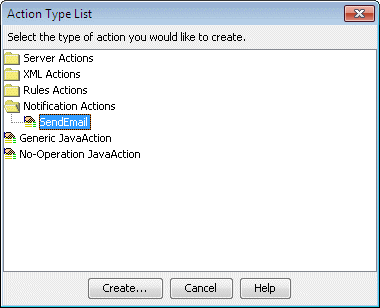
Select Timer Actions and then click the Add button. In the action type list dialog box that is displayed, select Notification Actions >> SendEmail
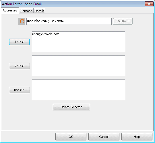
Select the Addresses tab in the Send Email dialog box that is displayed and then enter the email recipient address.
If enter the email address by E mode,Enter the email address with double quotation mark.
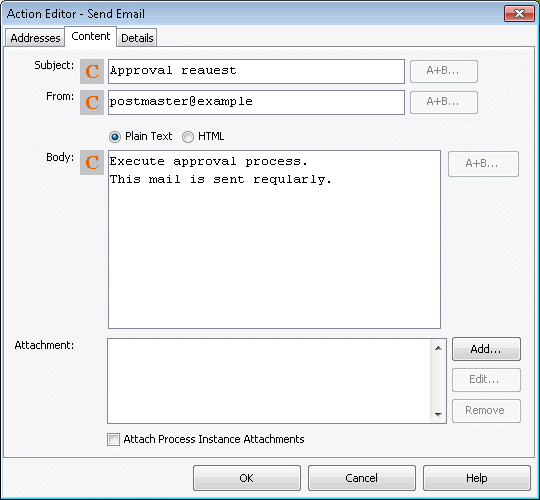
Select the Content tab in the Send Email dialog box and then enter the subject and text of the email.
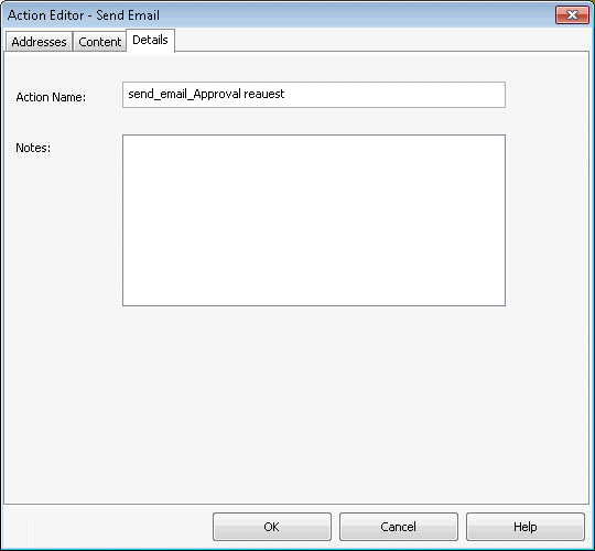
You can add any name or description to the outgoing email action by selecting the details tab of the Send Email dialog box.
When you click the OK button in the Send Email dialog box, the settings are complete.
A process definition that has the email notification setting enabled will be displayed as shown below.
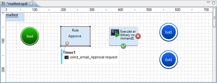
It is possible to execute the same operation for multiple targets and create Automated Operation Processes for execution of the same operation multiple times.
Using the Compound Activity Node, it is possible to create an Automated Operation Process for the repeated execution of a series of tasks for multiple servers, such as stopping the operating system after the job application has stopped.
Using the "Check that the specified time has elapsed" operation component, it is possible to execute the same operation repeatedly until a fixed time elapses. As with the confirmation that the startup is completed after the server startup request is received, it is possible to create an Automated Operation Process for the execution of operations that are treated as abnormal startups because the startup cannot be confirmed even though the fixed time has elapsed.
The following operation components can be multiple specified operation objects such as confirmed service name.
The same operation for multiple operations can be done collectively, such as checking multiple services have started.
Operation components | Objects of batch operation |
|---|---|
Check that service has started | The service which checked start |
Check port connection | The port number which checked connect |
Check server running normally | The service which checked start, and the port number which checked connect |
Check operational status of node | The node which checked operate |
Start the server | The server which started |
Stop the server | The service which stopped |
Stop OS | The server which stop OS |
Restart OS | The server which restart OS |
Start virtual server | The virtual server which started |
Stop virtual server | The virtual server which stopped |
Restart virtual server | The virtual server which restarted |
Using the "Execute multi-operation processes" operation component, other Automated Operation Processes can be executed concurrently. An Automated Operation Process, that defines the finite processing used for multiple Automated Operation Processes, can also be called. Additionally, by executing the operation component once, Automated Operation Processes can be executed with multiple servers as operation targets.
While the operation target is being changed, it is possible to execute the same operation repeatedly.
The procedure to create an Automated Operation Process for the repeated execution of the operation to stop the server after the service has stopped is shown below.
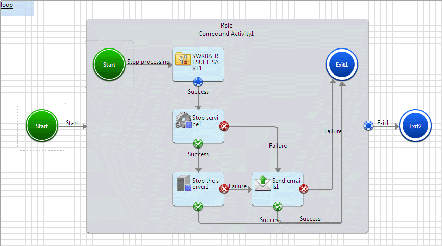
Click the Compound Activity in the Basic tab. With the Process Definition Editor, add the Compound Activity Node by pointing and clicking in the area where it should be placed.
Click the Store data as execution results in the Operation process control tab. With the Process Definition Editor, add the operation component node by pointing and clicking in the Compound Activity Node area where it should be placed.
Click the Stop the service in the Service/Process Operations tab. With the Process Definition Editor, add the operation component node by pointing and clicking in the Compound Activity Node area where it should be placed.
Click the Stop the server in the Server operations tab. With the Process Definition Editor, add the operation component node by pointing and clicking in the Compound Activity Node area where it should be placed.
Click the Send emails in the Email Operations tab. With the Process Definition Editor, add the operation component node by pointing and clicking in the Compound Activity Node area where it should be placed.
Click the Exit in the Basic tab of the Palette. With the Process Definition Editor, add the Exit Node by pointing and clicking in the Compound Activity Node area where it should be placed.
Click the Exit in the Basic tab of the Palette. With the Process Definition Editor, add the Exit Node by pointing and clicking in the area where it should be placed.
Each node is joined by an arrow. Set an arrow name if necessary.
Create the user defined attribute (UDA) for storing common information host names to be used in multiple operation components:
Select the Properties >> User Defined Attributes tabs.
Click the Add button to add the user defined attribute (UDA).
Here, the following UDAs are added:
UDA name | Type | Default value |
|---|---|---|
hostlist | STRING | The operation target server host name is set in the following format: |
hostname | STRING | No initial value is set. |
counter | INTEGER | This UDA is used as a counter for repetitive operations. By default, the UDA is set to 0. |
Set the properties for the Compound Activity Node that was positioned.
With the Process Definition Editor, click the Compound Activity Node that the input information is set on. Click the Properties >> General tabs, and set the properties.
Set the following for the Sequential Loop property.
Item name | Settings value |
|---|---|
Condition | Clear the checkbox. The conditions are not specified here. |
Count | Select this checkbox, and specify the number of servers to be operated. |
Set the input information for the operation component node that was positioned.
With the Process Definition Editor, click the operation component node that the input information is set on. Click the Properties >> IO Setting >> Input Data tabs and set the input information.
The content that can be set for the input information is shown below:
Operation component name | Option name | Settings value |
|---|---|---|
Stop service | hostname | Set the host name. Here, select Variable (uda) as the type and set hostname. |
service | Set the name of the service to be stopped. | |
Stop the server | hostname | Set the host name. Here, select Variable (uda) as the type and set hostname. |
Send emails | hostname | Specify the host name or IP address for the SMTP server. |
fromaddress | Set the email address of the sender. | |
toaddress | Set the email address of the recipient. | |
subject | Set the subject line for the email. | |
text | Set the body of the email. |
In the repeated processing, the operation target host name is set as UDA: hostname.
Set the I/O information for the Store data as execution results operation component that was placed.
With the Process Definition Editor, click the Store data as execution results operation component.
Click the Properties >> IO Setting >> Input Data tabs and set the input information.
The content that can be set for the input information is shown below:
Option name | Settings value |
|---|---|
input1 | Set the data that is to be edited. Here, select Variable (uda) as the type and set counter. |
input2 | Set the data to be edited. Here, select Variable (uda) as the type, and set hostlist. |
Click the Output Data tab and set the output information.
Click the Add button, then select the uda that has been added to the list in the Output Data tab, then enter the following information:
Execution results | Variable name |
|---|---|
result1 | counter |
result2 | hostname |
Select counter, and click the Add button for Define Filter.
The Filter settings dialog box will be displayed.
Select Calculate from the List of filters, and click the Add button.
Set the following in the Define Filter area, and click OK.
Item name | Settings value |
|---|---|
Calculation method | Select Add. |
Operation value type | Select Fixed value. |
Addition value | Set "1". |
Select hostname from the Output Data section list, and click the Add button for Define Filter.
Filter settings dialog will be displayed.
From List of filters, select "Extract CSV data", then click the Add button.
Set the following in the Define Filter area, and click the OK button.
Item name | Settings value |
|---|---|
Delimiter | Select Comma. |
Enclose with | Select Double quotes. |
Treat the first row as the header | Do not select. |
Sort condition | Optional. |
Row to be extracted | Optional. |
Column to be extracted | Specify the UDA that is assigned to the counter. Specify counter here. |
It is possible to execute the same operation repeatedly until a fixed time elapses.
The procedure to create an Automated Operation Process for the execution of the startup confirmation at 30 second intervals for a maximum of 5 minutes after the server startup request was received is shown below.

Click Start the server in the Server operations tab. With the Process Definition Editor, add the operation component node by pointing and clicking in the area where it should be placed.
Click Check that the specified time has elapsed in the Operation process control tab. With the Process Definition Editor, add the operation component node by pointing and clicking in the area where it should be placed.
Click Check operational status of node in the Network operations tab. With the Process Definition Editor, add the operation component node by pointing and clicking in the area where it should be placed.
Click Send emails in the Email Operations tab. With the Process Definition Editor, add the operation component node by pointing and clicking in the area where it should be placed.
Click Exit in the Basic tab of the Palette. With the Process Definition Editor, add the Exit Node by pointing and clicking in the area where it should be placed.
Each node is joined by an arrow. Set an arrow name if necessary.
Create the user defined attribute (UDA) for storing common information host names to be used in multiple operation components.
Select the Properties >> User Defined Attributes tabs.
Click Add to add the user defined attribute (UDA).
Additionally, as the initial value of the UDA, set "hostname" as the host name of the server that will execute the operation.
Set the input information for the operation component node that was positioned.
With the Process Definition Editor, click the operation component node that the input information is set on. Click the Properties >> IO Setting >> Input Data tabs and set the input information.
The content that can be set for the input information is shown below:
Operation component name | Option name | Settings value |
|---|---|---|
Start the server | hostname | Set the host name. Here, select Variable (uda) as the type and set hostname. |
Check that the specified time has elapsed | iteration_duration | Set the repeat processing time. Here, set "300". |
iteration_sleep_time | Set the repeat processing wait time. Here, set "30". | |
Check operational status of node | hostname | Set the host name. Here, select Variable (uda) as the type and set hostname. |
Send emails | hostname | Specify the host name or IP address for the SMTP server. |
fromaddress | Set the email address of the sender. | |
toaddress | Set the email address of the recipient. | |
subject | Set the subject line for the email. | |
text | Set the body of the email. |
Batch operations can be executed for multiple identical operations, such as confirmation that the service has started up.
The procedure to create an Automated Operation Process for the batch execution of the confirmation that multiple services have started up, after the node operational status for the Automated Operation Process created in "3.2.3.9.2 Repeatedly execute same operation within a fixed time" has been checked, is shown below.

Click Check that the service has started in the Service/Process Operations tab With the Process Definition Editor, add the operation component node by pointing and clicking in the area where it should be placed.
Click Send emails in the Email Operations tab. With the Process Definition Editor, add the operation component node by pointing and clicking in the area where it should be placed.
Each node is joined by an arrow. Set an arrow name if necessary.
Set the input information for the operation component node that was positioned.
With the Process Definition Editor, click the operation component node that the input information is set on. Click the Properties >> IO Setting >> Input Data tabs and set the input information.
The content that can be set for the input information is shown below:
Operation component name | Option name | Settings value |
|---|---|---|
Check that the service has started | hostname | Set the host name. Here, select Variable (uda) as the type and set hostname. |
service | Set the list of service names for which the startup is to be checked. Set the service names in the following format: "service 1","service 2","service 3",... | |
Send emails | hostname | Specify the host name or IP address for the SMTP server. |
fromaddress | Set the email address of the sender. | |
toaddress | Set the email address of the recipient. | |
subject | Set the subject line for the email. | |
text | Set the body of the email. |
Multiple Execution of Automated Operation Process can be done by differential setting, such as executing same contents of processing to multiple server
The procedure to create an Automated Operation Process that was created in "3.2.3.9.3 Batch Operations for Multiple Operation Targets" as the Automated Operation Process that is executed for the Windows server registered in CMDB is shown below.
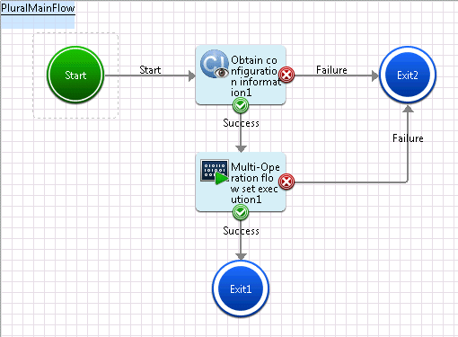
Click the Obtain configuration information in the Configuration item operations tab. With the Process Definition Editor, add the operation component node by pointing and clicking in the area where it should be placed.
Click the Store data as execution results in the Operation process control tab. With the Process Definition Editor, add the operation component node by pointing and clicking in the area where it should be placed.
Click the Multi-Operation flow set execution in the Command execution tab. With the Process Definition Editor, add the operation component node by pointing and clicking in the area where it should be placed.
Click the Exit in the Event folder under the Basic tab of the Palette. With the Process Definition Editor, add the Exit node by pointing and clicking in the area where it should be placed.
Each node is joined by an arrow. Set an arrow name if necessary.
Create the user defined attribute (UDA) for storing the input information of the Execute multi-operation processes operation component.
Select the Properties >> User Defined Attributes tabs.
Click Add to add the user defined attribute (UDA).
Here, the UDA name is "param". No initial value is set for the UDA.
Set the input information for the Obtain configuration information operation component that was positioned.
Click the Obtain configuration information operation component on the Process Definition Editor. Click the Properties >> IO Setting >> Input Data tabs and set the input information.
The content that can be set for the input information is shown below:
Option name | Settings value |
|---|---|
hostname | Set the CMDB host name. Here, select Value(fixed) as the type and set localhost. |
serachpath | Specify a conditional expression for acquiring the configuration information. Here, select Value(fixed) as the type and set the following: /%LogicalServer[(./#observed/rc:LogicalServer/rc:SystemSettings/rc:OSSetting[matches(@@name,'Windows.*')])] |
Set the input information for the Execute multi-operation processes operation component that was positioned.
With the Process Definition Editor, click the Execute multiple operation processes operation component. Click the Properties >> IO Setting >> Input Data tabs and set the input information.
The content that can be set for the input information is shown below:
Option name | Settings value |
|---|---|
subflowname | Name of the process definition that was created in "3.2.3.9.3 Batch Operations for Multiple Operation Targets". |
parameters | Set the information that will be passed to the Automated Operation Process that will be executed. Here, select Variable (uda) as the type and set param. |
Set the UDA: param value that will be used as the input information for the Execute multi-operation processes operation component.
Set the output information for the Obtain configuration information operation component that was positioned.
Click the Obtain configuration information operation component on the Process Definition Editor. Click the Properties >> IO Setting >> Output Data tabs and set the output information.
Click the Add button, then select the UDA that has been added to the list in the Output Data tab, then set the following value:
Execution results | Variable name |
|---|---|
ci_get_result | param |
Click the Define Filter >> Add button.
Filter settings dialog will be displayed.
From List of filters, select Extract XML attribute, then click the Add button.
The following are set in the Define Filter area:
Item name | Settings value |
|---|---|
XPath | Set the following string: /entities/item/record/LogicalServer |
Attribute name | Select the following string:
|
Delimiter | Select Line feed. |
From the server information that was obtained from CMDB, use a delimiter to extract the server names.
From List of filters, select Format, then click the Add button.
The following are set in the Define Filter area:
Item name | Settings value |
|---|---|
Delimiter | Select "Comma". |
Enclose with | Select Double quotes. |
Format string | Set the strings shown below. In $number, a serial number that starts with 1 is set. In {0}, the server names that were extracted using the delimiter are set. <Parameter ID="[$number]"> |
From List of filters, select "Add string", then click the Add button.
The following are set in the Define Filter area:
Item name | Settings value |
|---|---|
Text | Set the following strings: <?xml version="1.0" encoding="UTF-8"?> |
Application method | Select Apply for all. |
Text location | Select Add to Start. |
From List of filters, select "Add string", then click the Add button.
The following are set in the Define Filter area:
Item name | Settings value |
|---|---|
Text | Set the following string: </ParameterSet> |
Application method | Select Apply for all. |
Text location | Select Add to end. |
With using Button items, Able to add help button in form.
The processing to add help button in form is shown below.
Select Button item in Basic folde of Palette. In Design Editor, Click the locale where to deploy items, and add Button item.
Seelect Property >> Attribute tab, Change type value from "submit" to "button".
Input button label in value.Here, Input Help as a button label.
Input URL of help displayed in value of onclick with the following format.Here, Input " http://example.com/index.html ", for example.
onclick: window.open('http://example.com/index.html')

Click Help button, Specified help documents of URL is displayed with another windows.