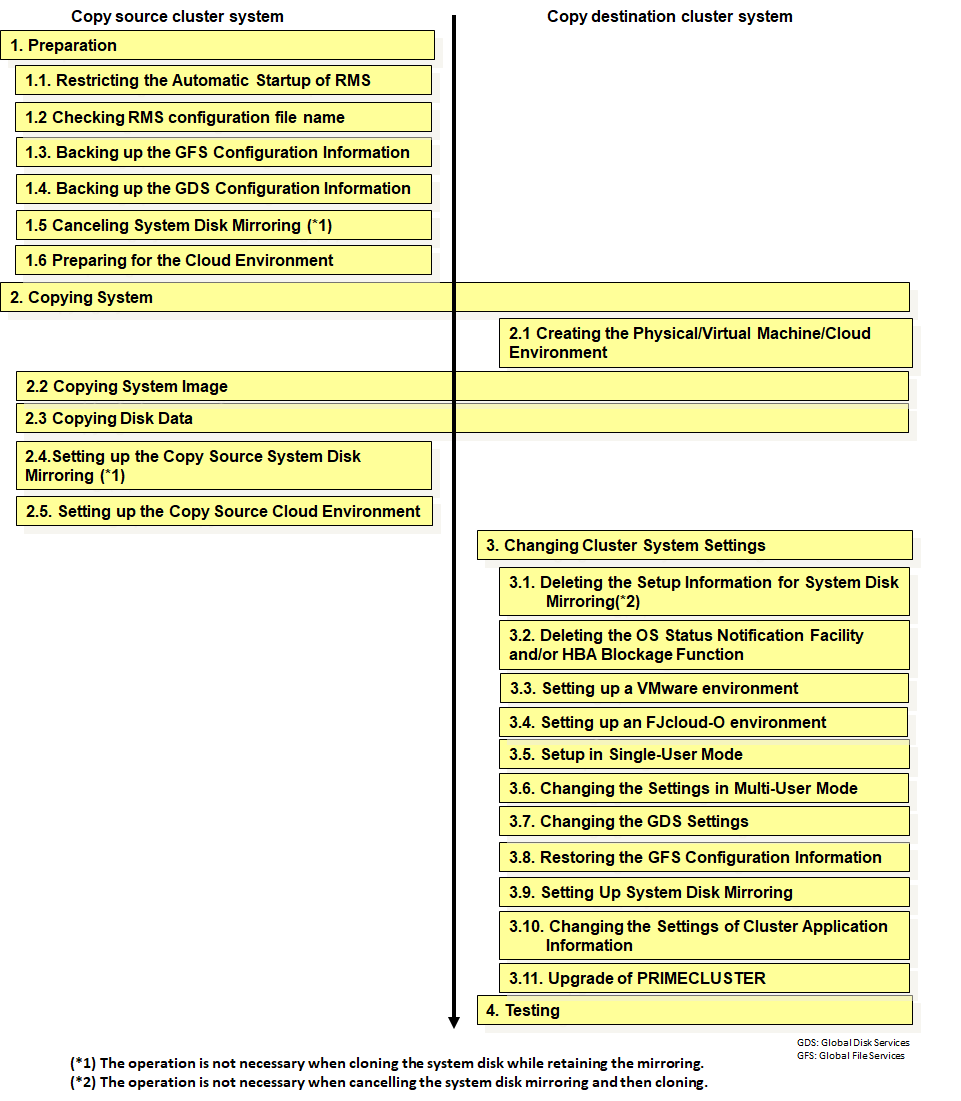
Different copy patterns require different tasks. Refer to the table below to perform the required tasks according to the copy pattern.
The cluster system copy has the following patterns:
Between physical environments (Cloning/P2P)
Between VMware environments (Cloning/V2V)
Between KVM environments (Cloning/V2V)
Between FJcloud-O environments (Cloning/V2V)
Replication from physical to virtual (VMware) (P2V)
No. | Work | copy pattern | |||||||||||
|---|---|---|---|---|---|---|---|---|---|---|---|---|---|
a | b | c | d | e | |||||||||
Preparation | |||||||||||||
1 | ++ | ++ | ++ | ++ | ++ | ||||||||
2 | ++ | ++ | ++ | ++ | ++ | ||||||||
3 | + | + | + | - | + | ||||||||
4 | + | + | + | + | + | ||||||||
5 | + | + | - | - | + | ||||||||
6 | - | - | - | ++ | - | ||||||||
Copying System | |||||||||||||
7 | K.4.1 Creating the Physical/Virtual Machine/Cloud Environment | ++ | ++ | ++ | ++ | ++ | |||||||
8 | ++ | ++ | ++ | ++ | ++ | ||||||||
9 | ++ | ++ | ++ | ++ | ++ | ||||||||
10 | + | + | - | - | + | ||||||||
11 | - | - | - | ++ | - | ||||||||
Changing Cluster System Settings | |||||||||||||
12 | K.5.1 Deleting the Setup Information for System Disk Mirroring | + | + | - | - | + | |||||||
13 | K.5.2 Adding and Deleting the OS Status Notification and/or HBA Blockage Function | + | - | - | - | ++ | |||||||
14 | - | + | - | - | ++ | ||||||||
15 | - | - | - | + | - | ||||||||
16 | ++ | ++ | ++ | ++ | ++ | ||||||||
17 | ++ | ++ | ++ | ++ | ++ | ||||||||
18 | + | + | + | + | + | ||||||||
19 | + | + | + | - | + | ||||||||
20 | + | + | - | - | + | ||||||||
21 | K.5.10 Changing the Settings of Cluster Application Information | ++ | ++ | ++ | ++ | ++ | |||||||
22 | + | + | + | + | + | ||||||||
23 | ++ | ++ | ++ | ++ | ++ | ||||||||
++:Required, +: Set as needed, -:Unrequired
RMS: Reliant Monitor Services
GFS: Global File Services
GDS: Global Disk Services
Here, the copying procedure is explained with the cases of copying a two-node, operation-standby cluster system.
Figure K.3 Procedure for Copying the Cluster System

The description of the steps in the following execution example, is given for building a cluster system with the following configuration.
Copy source | Copy destination | |||
|---|---|---|---|---|
Cluster name | PRIMECLUSTER1 | PRIMECLUSTER2 | ||
CF node name | fuji2 | fuji3 | fuji4 | fuji5 |
CIP/SysNode name | fuji2RMS | fuji3RMS | fuji4RMS | fuji5RMS |
IP address of administrative LAN | 10.20.30.100 | 10.20.30.101 | 10.20.30.102 | 10.20.30.103 |
IP address for IPMI (BMC or iRMC) or IP address of management blade | 10.20.30.200 | 10.20.30.201 | 10.20.30.202 | 10.20.30.203 |
IP address for CIP | 192.168.0.1 | 192.168.0.2 | 192.168.0.3 | 192.168.0.4 |
IP address for cluster interconnect | 172.16.0.1 | 172.16.0.2 | 172.16.1.3 | 172.16.1.4 |
Class name of GDS | Class1 | |||
Physical IP address/hostname for GLS | 10.34.214.181/primecl01 | 10.34.214.182/primecl02 | 10.34.214.191/primecl03 | 10.34.214.192/primecl04 |
Virtual IP address/hostname for GLS | 10.34.214.185/takeoverIP | 10.34.214.195/takeoverIP2 | ||
GDS: Global Disk Services
GLS: Global Link Services