Set the HUB monitoring function for the operation in NIC switching mode. Set the HUB monitoring function in accordance with the following procedure:
Figure 3.6 Setting procedure of the HUB monitoring function
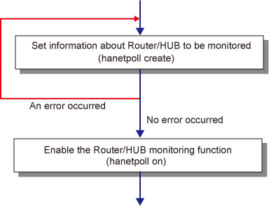
Create the monitoring information of the HUB monitoring function. Use the "hanetpoll" command for this setting. For details about this command, see Section "7.7 hanetpoll Command".
Enable the HUB monitoring function.
Use the "hanetpoll on" command to set up this function. If the "hanetpoll on" command is executed, the ping command is executed on the HUB.
Note
In NIC switching mode, no line failure is assumed until the link up wait time (IDLE (seconds) in Figure 3.7 Basic sequence of HUB monitoring) passes even if the ping command fails. This is because monitoring starts after a physical interface is activated. Time required for link up depends on the HUB type to be connected. If the line monitoring fails although the HUB is not faulty, extend the wait time as required, using the -p parameter of the "hanetpoll on" command.
For more information, see Section "7.7 hanetpoll Command".
Figure 3.7 Basic sequence of HUB monitoring
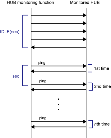
Figure 3.8 HUB monitoring sequence after detect line fault
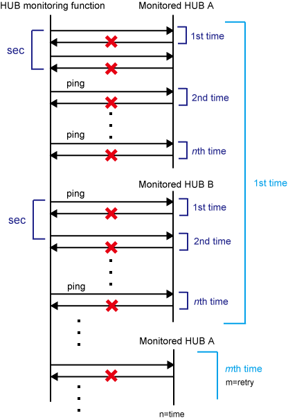
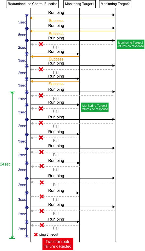
This section describes on transfer route error detection sequence of HUB monitoring feature on NIC switching mode.
The following are examples of the case of one monitoring target and two monitoring targets. For one monitoring target, the HUB-to-HUB monitoring target is disabled in a NIC redundant configuration or one HUB monitoring target is set in a single physical interface configuration. For two monitoring targets, the HUB-to-HUB monitoring target is enabled in a NIC redundant configuration or two HUB monitoring targets are set in a single physical interface configuration.
One monitoring target:
Error detection time = monitoring interval (in seconds) X (monitoring frequency - 1) + ping time out period(*1) + (0 to monitoring interval (in seconds)) |
*1: If the monitoring interval is 1 second, ping time out period would be 1 second, otherwise, ping time out period would be 2 seconds.
The default value is as follows.
5 sec x (5 time - 1) + 2 sec + 0 to 5 sec = 22 to 27 sec
Two monitoring targets:
Error detection time = monitoring interval(in seconds) X (monitoring frequency - 1) + ping time out period (*2) x 2 (0 to monitoring interval(in seconds)) |
*2: If the monitoring interval is 2 seconds, ping time out period would be 1 second, otherwise, ping time out period would be 2 seconds.
The default value is as follows.
5 sec x (5 time - 1) + 2 sec x 2 time + 0 to 5 sec = 24 to 29 sec
Figure 3.9 Transfer path error detection sequence (one monitoring target)
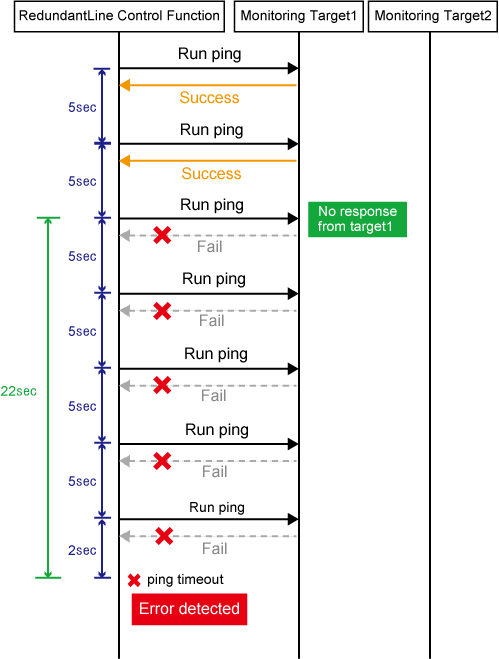
Figure 3.10 Transfer path error detection sequence (two monitoring target)
If the link status monitoring function is enabled, the link state is checked immediately after a ping failure to the primary monitoring destination (monitoring destination 1). If the link is down, the link status monitoring function determines that the transfer route failed.
One monitoring target:
Error detection time = ping time out period(*3) + (0 to monitoring interval (in seconds)) |
*3: If the monitoring interval is 1 second, ping time out period would be 1 second, otherwise, ping time out period would be 2 seconds.
The default value is as follows.
2 sec + 0 to 5 sec = 2 to 7sec
Two monitoring targets:
Error detection time = ping time out period (*4) x 2 (0 to monitoring interval (in seconds)) |
*4: If the monitoring interval is 2 seconds, ping time out period would be 1 second, otherwise, ping time out period would be 2 seconds.
The default value is as follows.
2 sec x 2 time + 0 to 5 sec = 4 to 9 sec
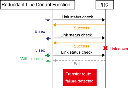
When not using monitoring by ping command:
Error detection time = 1 sec + (0 to monitoring interval (in seconds)) |
The default value is as follows.
1 sec + 0 to 5 sec = 1 to 6 sec
Figure 3.11 Transfer path error detection sequence with link down (one monitoring destination)
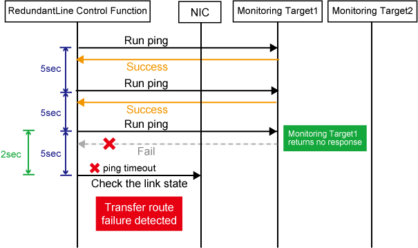
Figure 3.12 Transfer path error detection sequence with link down (two monitoring destinations)
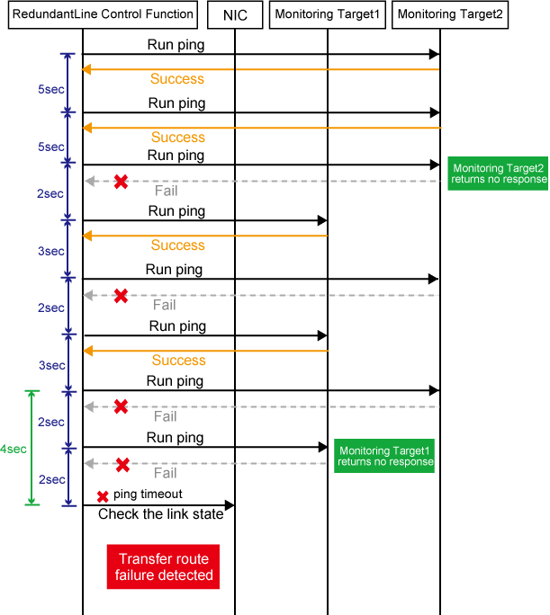
Figure 3.13 Transfer path error detection sequence with link down (when not using monitoring by ping command)
Information
Since ping monitoring is performed at regular intervals (in seconds), the maximum interval of time is required between the time the monitoring destination fails and the time the next ping is sent. Therefore, it takes at least 22 seconds and up to 27 seconds to detect the failure after a failure has occurred. In addition, if the transfer route failure due to NIC link down is detected, it takes at least 2 seconds and up to 7 seconds for GLS to detect the transfer route failure after notification (to the system log, etc) that the NIC link is down message was sent.
Just after starting error monitoring for transfer routes, e.g. just after activation of virtual interfaces or NIC switching, error detection will be pended until the waiting time for linkup elapses.
In an environment where GLS is used on the host OS of the virtual machine function, the NIC link down cannot be detected by the link status monitoring function. This is because the link down is not notified to a physical interface bundled by GLS and connected via a virtual switch, even if the NIC link down of the host OS is detected by the link status monitoring function. Therefore, the line will be switched after an error is detected by the HUB monitoring function instead of by the link status monitoring function.
Note
If no response after the ping command run for 30 seconds, the hang-up will be detected and it will be determined that an error has occurred on the transfer route before running the command again.