This section describes on transfer route multiplexing using tagged VLAN interfaces.
Note
Transfer route multiplexing with tagged VLAN is not available in GS linkage modes.
See
If you use tagged VLAN interfaces on GLS, configure network. See "3.2.2 Network configuration".
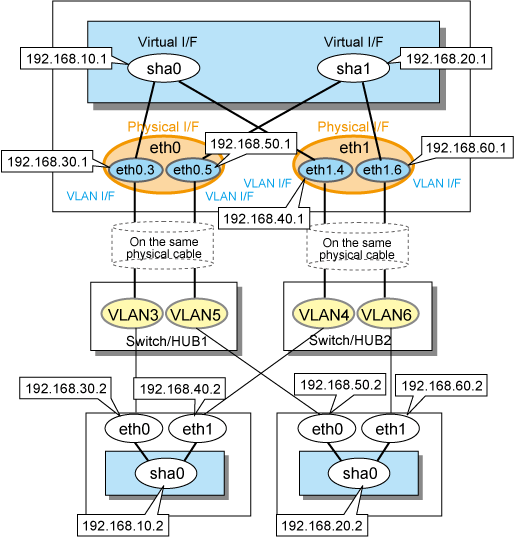
When bundling a tagged VLAN interface on Fast switching mode, specify the tagged VLAN interface instead of the physical interface. Figure 3.2 Fast switching mode with tagged VLAN interface illustrates bundled tagged VLAN architecture.
Note
You cannot create a virtual interface by bundling two tagged VLAN interfaces emerged from a single physical interface. Please be sure to specify the tagged VLAN interfaces on disparate physical interfaces when creating a virtual interface for Fast switching mode.
See
Refer to "7.1 hanetconfig Command" for configuring an interface bundled with Fast switching mode.
Figure 3.2 Fast switching mode with tagged VLAN interface illustrates an example of using tagged VLAN interface on Fast switching mode.
Figure 3.2 Fast switching mode with tagged VLAN interface

When using a tagged VLAN interface on NIC switching mode, specify the tagged VLAN interface instead of a physical interface at configuration.
In addition, when tagged VLAN interfaces on the same physical network cable is made redundant by two or more virtual interfaces, the mode to "synchronous switching" or "asynchronous switching" operation is defined. Below, operation of "synchronous switching" and "asynchronous switching" is explained.
Redundant network methods | Switchover | ||
|---|---|---|---|
Synchronous | Asynchronous | ||
NIC switching mode (Logical IP takeover) | IPv4 | Enabled | Enabled |
IPv6 | Enabled | Enabled | |
Dual | Enabled | Enabled | |
NIC switching mode (Physical IP takeover) | IPv4 | Disabled | Enabled |
See
For configuration of monitoring target, refer to "7.7 hanetpoll Command".
Synchronous switching
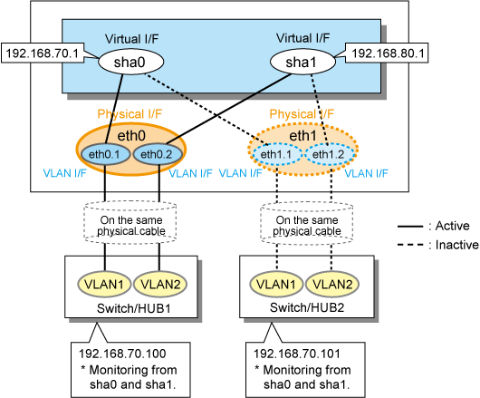
In two or more virtual interfaces which bundle multiple tagged VLAN interfaces redundantly, by defining the same monitoring target IP address, all virtual interfaces are synchronous switching, when failure occurs in monitoring of transfer path. When the switch/HUB of a monitoring target has only one IP address, "synchronous switching" of a virtual interface is chosen.
Figure 3.3 NIC switching mode with tagged VLAN interface (synchronous switching) illustrates of synchronous switching architecture.
Figure 3.3 NIC switching mode with tagged VLAN interface (synchronous switching)

In the above figure, sha0 and sha1 of the network interfaces monitor the same IP address. If a transmission route failure is detected on sha0, virtual interface switching of sha1 as well as sha0 will occur,
Asynchronous switching
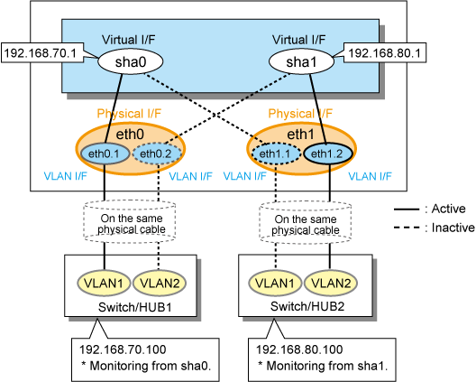
Two or more virtual interfaces that bundle the tagged VLAN interface can be asynchronously switched. In this case, the monitoring target IP address from which it differs for every virtual interface is defined as monitoring target information. When two or more definitions of the IP address are possible to switch/HUB used as a monitoring target, the asynchronous switching of the virtual interfaces is chosen to use Standby NIC effectively.
Figure 3.4 NIC switching mode with tagged VLAN interface (asynchronous switching) illustrates of asynchronous switching architecture.
Figure 3.4 NIC switching mode with tagged VLAN interface (asynchronous switching)

In the above figure, sha0 and sha1 of the network interfaces monitor the different IP addresses respectively. If a transmission route failure is detected on sha0, and virtual interface switching of sha0 occurs, that of sha1 will not occur.
Note
On NIC switching mode, if several tagged VLAN interfaces exist on two physical interfaces, and at lease two virtual interfaces are created on pairs of those tagged VLAN interfaces, please ensure that you configure the standby patrol function exclusively on a single virtual interface. For example, say virtual interface (sha0) is created on two tagged VLAN interfaces "eth0.1" and "eth1.1", and similarly, another virtual interface (sha1) is created on "eth1.2" and "eth0.2", the standby patrol function must be configured on either one of the virtual interfaces (sha0 or sha1).
On NIC switching mode, tagged VLAN interfaces on a pair of physical interfaces should be used to create multiple virtual interfaces, if tagged VLAN networks are used. For example, you cannot have an environment where a virtual interface is created on a pair of VLAN interfaces "eth0.1" and "eth1.1", and another virtual interface is created on a pair of VLAN interfaces "eth1.2" and "eth2.2" because the physical interface "eth1" is the only shared physical interface here.
If you specify two monitoring targets with synchronous switching mode, please specify two network addresses which belong to the same network. If their network addresses are different, switch/HUB monitoring cannot operate normally, because they are assigned to only one virtual interface.
When the physical IP address takeover function of the NIC switching mode is used, a virtual interface cannot be synchronous switched.
If you want to share physical connections between a virtual interface bound to physical interfaces and a virtual interface bound to tagged VLAN interfaces, set the standby patrol for each virtual interface. For example, as shown below, if the virtual interface sha0 uses "eth0" and "eth1," and the virtual interface sha1 uses "eth1.2" and "eth0.2, set the standby patrol (sha2 and sha3) for both virtual interfaces.
# /opt/FJSVhanet/usr/sbin/hanetconfig print [IPv4,Patrol / Virtual NIC] Name Hostname Mode Physical ipaddr Interface List +-----------+---------------+----+-----------------+---------------------------+ sha0 192.168.10.110 d 192.168.10.10 eth0,eth1 sha1 192.168.12.110 d 192.168.12.10 eth0.2,eth1.2 sha2 - p - sha0 sha3 - p - sha1 |
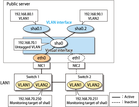
In Virtual NIC mode, you can generate a tagged VLAN interface on the virtual interface for communication. It is also possible to mix tagged and untagged communication.
The following Figure 3.5 Virtual NIC mode with tagged VLAN interface shows an example.
Figure 3.5 Virtual NIC mode with tagged VLAN interface

Note
You cannot bundle tagged VLAN interfaces (ethX.Y, VLANX etc.) in Virtual NIC mode.