In this mode, each of multiple NIC (Network Interface Card) is connected to a different network and all of these NICs are activated and then used concurrently. Each outgoing packet is transmitted via an appropriate line according to the line conditions (whether or not any failure has occurred).
Also, an interface that is virtual (called a virtual interface in this document) is generated so that multiple NICs can be seen as one logical NIC. A TCP/IP application can conduct communication with the remote system, irrespective of the physical network redundant configuration, by using an IP address (called a virtual IP address in this document) set in this virtual interface as its own IP address of the local system.
Figure 2.1 Example of duplicated operation in Fast switching mode
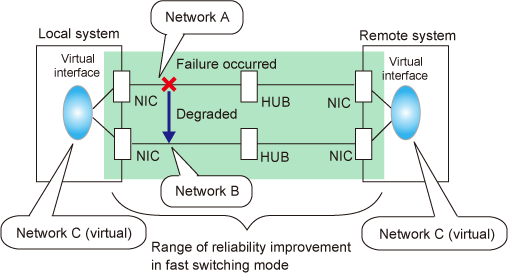
A system with which communication is to be carried out is connected to the same network and is not allowed to connect to a different network.
In the event of a failure, lines can be switched swiftly in a short period of time without affecting the applications. Since redundant lines are all activated, each line can be used for different purposes, enabling the efficient use of resources.
This mode is appropriate, for example, to communications between the application server and database server in a three-tier client-server system.
Figure 2.2 System configuration for Fast switching mode shows a system configuration for Fast switching mode:
Figure 2.2 System configuration for Fast switching mode
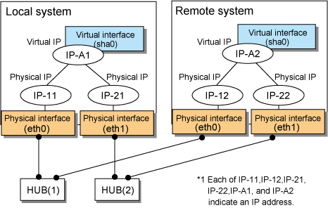
The following explains each component and its meaning:
Indicates a physical interface (such as eth0 and eth1) of the duplicated NIC.
Indicates an IP address attached to a physical interface. This IP address is always active.
Available IP addresses are IPv4 and IPv6 address.
Indicates a virtual interface (such as sha0) so that the duplicated NIC can be seen as one NIC.
Indicates a source IP address to be allocated to the virtual interface for communication with the remote hosts. Available IP addresses are IPv4 and IPv6 address.
Sends a dedicated monitor frame to the other system's NIC at regular intervals (a default value is five seconds. It is possible to change by the hanetparam command) and waits for a response. When received a response, decides that a route is normal, and uses it for communication until next monitoring. When received no response, decides that an error occurred, and not use it for communication until decides it is normal at next monitoring. Monitoring is done in each NIC unit that the other device equips.
Figure 2.3 Monitoring method in Fast switching mode
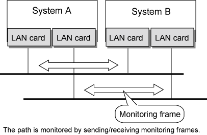
If a failure occurs in a multiplexed line, it takes approximately 10 seconds to disconnect the line.
The following failures can be detected:
Figure 2.4 Detectable failures in Fast switching mode
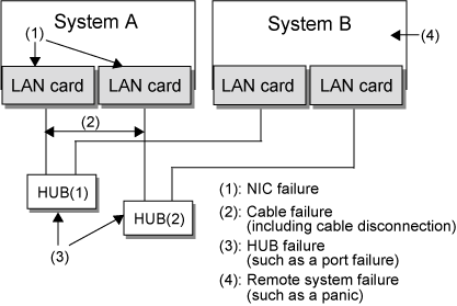
Because the failures (1) - (4) appear to be the same failure, a type of the failure cannot be specified. Each device has to be checked to make this determination.
Monitoring is started automatically when the virtual interface is activated. Monitoring is automatically stopped when the virtual interface is inactivated. In cluster operation, the system allows each node to be started or stopped independently.
A line whose failure is detected is automatically avoided, and the only normal line takes over the communication. Therefore, if at least one normal line remains, the communication can continue without rebooting the system. It is also possible to disconnect a specific line manually by using the operational command (hanetnic command).
Figure 2.5 Outline of switching operation performed when a failure occurs in Fast switching mode
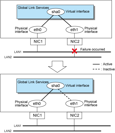
If the faulty line of a physical interface is recovered, the physical interface is automatically restored for normal communication. If a line was disconnected manually, the failback of the line needs to be performed manually to restore the original status.
An associated host is able to communicate with the following systems:
PRIMEQUEST
PRIMERGY
SPARC M10
SPARC Enterprise
PRIMEPOWER
The requirement for user applications that can be operated in this mode is as follows:
Application using the TCP or UDP.
When assigning IPv4 address to the virtual interface, IPv4 address must be assigned to all the redundant physical interfaces.
If assigning IPv6 address to the virtual interface, IPv6 address must be assigned to all the redundant physical interfaces.
If assigning both IPv4 and IPv6 to the virtual interface, these two forms of an IP address must be assigned to all the redundant physical interfaces.
No multi-cast IP address can be used.