The system is designed to enable clients, management servers, and monitoring nodes to configure with complete control.
Each topology is described below.
Note that the topology to be supported varies depending on the operation management product. For details, refer to the document for each operation management product.
Note
For details about setting the management server, refer to "7.3 Management server".
For details about setting network environment of management server, refer to "7.5 Multi-network between server and client by classified use".
For configuration of 3-tier model, refer to "2.4.1 Management server configuration".
2-tier architecture model
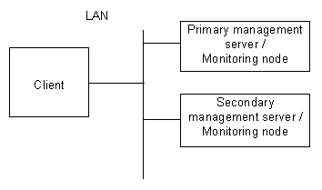
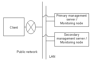
In this configuration, monitoring nodes and management servers share one tier, and a client is independent.
This model is relatively small-scale and is used when a management server is not set for specific purposes. It is a typical model primarily used for the cluster topology such as 1:1 standby and mutual standby in a two-node configuration.
It supports the following two types of topology:
Generic topology
In this topology, only one LAN is used for the Web-Based Admin View operation. This topology should be adopted only if the range of network and users can be limited and defined.
Topology where multi-network is used by classified use
In this topology, two LANs are used for Web-Based Admin View operation. The LAN used for communication among management servers and monitoring nodes and that used for the Web-Based Admin View screen of a client are separate. When using a client from a public network, this topology is recommended for security.
For the setup, designate the IP addresses for a client and a monitoring node respectively on the administration server.
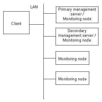
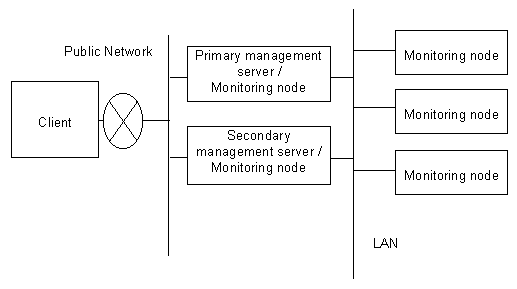
3-tier architecture model
In this configuration, monitoring nodes, management servers, and a client are allocated separately.
This model should be used especially when a large-scale PRIMECLUSTER system is managed centrally, or when a monitoring node should not be overloaded as a management server.
In case of the cluster system with three or more nodes, this model is used for N: 1 standby, mutual standby, or scalable operations.
For the configuration with three or more nodes, Fujitsu recommends this 3-tier architecture model in which the management server is installed separately to assure job continuity and availability.
This model supports the following two types of topology:
Generic topology
In this topology, only one LAN is used for the Web-Based Admin View operation. This topology should be adopted only if the range of network and users can be limited and defined.
Topology where multi-network is used by classified use
In this topology, two LANs are used for Web-Based Admin View operation. The LAN used for communication among management servers and monitoring nodes and that used for the Web-Based Admin View screen of a client are separate. When using a client from a public network, this topology is recommended for security.
For the setup, designate the IP addresses for a client and a monitoring node respectively on the management server.
Note
In three-tier configuration of Web-Based Admin View, server model and OS version of the cluster management server must be the same as those of cluster nodes.
Point
In the normal operation, the client, the management server, and the monitoring node of Web-based Admin View communicate one another by using the IP address of LAN, which is assigned to the displayed node name as a result of executing "uname -n." Note that the node name is referred to the name with which the communication network recognizes the system. The IP address is automatically set up when Web-Based Admin View is installed. When the LAN IP address of each host (node) is modified along with the system migration, the IP address should also be changed. For the modification method, refer to "7.1 Network address".