Configure defined setting information.
Configure the information defined in "4.2.2.1 Settings for the Admin Server" on the admin server.
The admin IP address should be specified when installing the manager on the admin server.
For details on how to configure the other information on the admin server, refer to the manual of the admin server.
Configure the information defined in "4.2.2.2 Settings for Admin Clients" on admin clients.
For details on how to configure information on admin clients, refer to the manual of the admin client.
Configure the information defined in "4.2.2.3 Settings for Managed Network Devices" on network devices.
In order to track the network connections between managed servers (PRIMERGY BX series) and adjacent network devices (L2 switches, etc.), and display them in the Network Map, the following protocols should be first enabled on each LAN switch blade and network device.
LLDP (Link layer Discovery Protocol)
CDP (Cisco Discovery Protocol)
Note
The same protocol needs to be set on the LAN switch blade and the network devices it is connected to.
It is not possible to automatically detect the connection relationship between LAN switch blades set in the IBP mode and network devices.
Network connections may not be displayed properly if two or more network devices are set with a conflicting system name (sysName).
For details on how to configure information on network devices, refer to the manual for each device.
Configure the information defined in "4.2.2.4 Settings for Unmanaged Network Devices" on the network devices.
For details on how to configure information on network devices, refer to the manual for each device.
Configure the information defined in "4.2.2.5 Settings for Managed Servers" on managed servers.
When the managed servers are rack mount or tower servers, configure the admin IP address on the network interfaces defined in the "Admin LAN for Servers" of "4.2.1.1 Admin LAN Network Design".
For details on how to configure information on managed servers, refer to the manual for the server.
Configure LAN switch blades on the managed blade systems using the information defined in "4.2.2.6 Settings for LAN Switch Blades on Managed Blade Systems".
For details on how to configure LAN switch blades on managed blade systems, refer to the manual of the LAN switch blade.
Information
VLAN settings for switch blade ports not used for the admin LAN can also be set from the [Resource] tab on the ROR console. For details, refer to "2.4.4 Configuring VLANs on LAN Switch Blades" of the "User's Guide for Infrastructure Administrators (Resource Management) CE".
Note
After setting up a LAN switch blade, perform a backup of the LAN switch blade's configuration definition information. For details how to backup the configuration definition information of a switch blade, refer to the manual of the LAN switch blade.
Resource Orchestrator uses telnet to log into LAN switch blades and automate settings.
When telnet connection is disabled, enable it.
Refer to the manual of the relevant product.
Some models of LAN switch blades may restrict the number of simultaneous connections. In this case, log out from other telnet connections.
If telnet is unavailable, the following features are also unavailable.
Registration of LAN switch blades
Changing of LAN switch blade settings
Changing and setting the VLAN for LAN switch blades (internal and external connection ports)
Restoration of LAN switch blades
Server switchover (changing network settings while a server is switched over)
For PY CB Eth Switch/IBP 10Gb 18/8, the maximum unregistered VLAN ID is used for the "oob" port in the LAN switch blade. When the maximum VLAN ID, "4094", is set in the LAN switch blade and the "oob" port is used to connect the telnet, the following functions cannot be used.
Changing and setting the VLAN for LAN switch blades (internal and external connection ports)
Restoration of LAN switch blades
Server switchover (changing network settings while a server is switched over)
When using end host mode, use the default pin-group and do not create new pin-groups. Also, disable the Auto VLAN Uplink Synchronization (AVS) setting.
If the VLAN settings are to be performed on the ports with link aggregation set on the following LAN switch blades, set the apparatuses as follows. Also, disable the Auto VLAN Uplink Synchronization (AVS) setting.
LAN switch blades
PY CB Eth Switch/IBP 10Gb 18/8+
Configuration
LLDP (Link layer Discovery Protocol)
When setting LLDP, make the setting for "VLAN name information" invalid.
Make the other settings valid.
However, settings other than VLAN settings should be made directly on the LAN switch blade.
Network Configuration of LAN Switch Blades (when using PRIMERGY BX Servers)
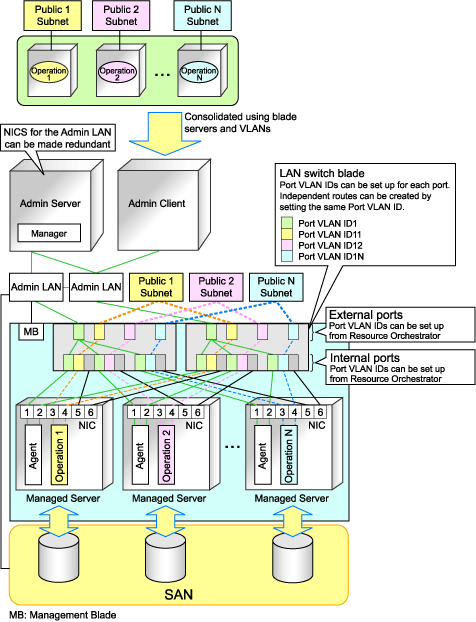
In a blade system environment, multiple subnets can be consolidated onto LAN switch blades by using VLANs.
For PRIMERGY BX900/BX400 LAN switch blades operating in IBP mode, the above can also be achieved by using port group settings for IBP instead of VLAN settings.
Each port of a LAN switch blade can be set with VLAN IDs.
Only those ports set with a same VLAN ID can communicate with each other.
Setting up different VLAN IDs then results in multiple subnets (one per VLAN ID) co-existing within the same switch.
Define the VLANs to set on both the internal (server blade side) and external connection ports of each LAN switch blade.
Internal Connection Ports
Ensure that port VLANs are configured for the ports corresponding to the NICs connected to the admin LAN.
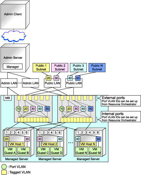
If NICs connected to the admin LAN are used for public LANs as well, configure tagged VLANs.
For the ports corresponding to the NICs connected to the public LAN, assign a VLAN ID (port or tagged VLAN) other than VLAN ID1 (the default VLAN ID) for each subnet.
Using tagged VLANs on LAN switch ports also requires configuring the network interfaces of managed servers with tagged VLANs. As Resource Orchestrator cannot set tagged VLANs to network interfaces on managed servers, this must be done manually.
External Connection Ports
Choose the LAN switch blade ports to connect to external LAN switches, and the VLAN IDs to use for both the admin and public LANs.
When choosing a tagged VLAN configuration, the VLAN ID chosen for a LAN switch blade's external port must be the same as that used on its adjacent port on an external LAN switch.
When using VLAN auto-configuration on the external ports of the LAN switch blades that compose the link aggregation, configure the link aggregation beforehand and enable the LLDP.
Refer to the manual for the LAN switch blade for information on how to configure link aggregation and to enable LLDP.
Note
To change the VLAN ID for the admin LAN, perform the following.
Enable communications between the admin server and the LAN switch blade.
Manually change the following two settings.
Change the VLAN ID of the external connection port(s) used for the admin LAN.
Change the VLAN ID used by the admin IP address of the LAN switch blade.
Change the VLAN ID used by the managed server on the admin LAN.
VLAN settings for LAN switch blades are not included in cloning images. Configure VLAN settings for the target servers before deploying a cloning image.
In the following cases, VLANs cannot be configured using the ROR console.
Configuring VLANs on external connection ports
Link state group
Port backup function
Configuring VLANs on external and internal connection ports
Link aggregation (excluding LAN switch blades PY CB Eth Switch/IBP 10Gb 18/8+)
Deactivated (depends on LAN switch blade model)
Choose VLAN IDs and VLAN types for the ports on the switches connected to NICs on the physical servers.
Physical server name
NIC index
VLAN ID
VLAN type (port or tagged VLAN)
Note
On servers, operating systems associate each physical network interface with a connection name (Local area connection X in windows and ethX in Linux).
If more than one network interface is installed, depending on the OS type and the order of LAN driver installation, the index numbers (X) displayed in their connection name may differ from their physically-bound index (defined by each interface's physical mount order).
The relations between physically-bound indexes and displayed connection names can be confirmed using OS-provided commands or tools.
For details, refer to network interface manuals.
Also, note that Resource Orchestrator uses the physical index of a network interface (based on physical mount order).
If the connection relationship (topology) between the managed server (PRIMERGY BX series) and neighboring network devices (L2 switches, etc.) is to be displayed in the network map, the following settings are required in the LAN switch blade and network device so that the topology can be automatically detected.
LLDP (Link layer Discovery Protocol)
CDP (Cisco Discovery Protocol)
Note
The same protocol needs to be set on the LAN switch blade and the network devices it is connected to.
It is not possible to automatically detect the connection relationship between LAN switch blades set in the IBP mode and network devices.
For the following LAN switch blades, the settings described below should be set to the same values in order to enable proper detection of network links.
LAN Switch Blades:
PY CB Eth Switch/IBP 1Gb 36/12
PY CB Eth Switch/IBP 1Gb 36/8+2
PY CB Eth Switch/IBP 1Gb 18/6
Expected Values:
hostname set from the hostname command
system name set from the snmp-server sysname command
Example
When setting both the hostname and system name to "swb1".
# hostname swb1
# snmp-server sysname swb1
For the following LAN switch blade, the settings described below should be set to the same value to enable proper detection of network links.
LAN Switch Blades
PY CB Eth Switch/IBP 10Gb 18/8
Configuration
Using the snmp agent address command, set the admin IP address of the LAN switch blade for the agent address.
Network connections may not be displayed properly if two or more network devices are set with a conflicting system name (sysName).
[Windows/Hyper-V]
When using the backup, restore, or cloning functions, enable the managed server's NetBIOS over TCP/IP.
Note that the managed server should be restarted after enabling NetBIOS over TCP/IP.
Example of VLAN Network Configuration (with PRIMERGY BX600)
Figure 4.15 With Port VLANs

Figure 4.16 With Tagged VLANs

Information
It is recommended that a dedicated admin LAN be installed as shown in "Example of VLAN network configuration (with PRIMERGY BX600)".
If you need to use the following functions, a dedicated admin LAN is required in order to allocate admin IP addresses to the managed servers using the DHCP server included with Resource Orchestrator.
Backup and restore
Collection and deployment of cloning images
HBA address rename
In a configuration using a LAN switch blade, a VLAN has to be configured if the LAN switch blade is shared by an admin and public LANs where a dedicated admin LAN is required.
Configure the information defined in "4.2.2.7 Settings for Managed Storage Units" on the managed storage.
For details on how to configure information on managed storage units, refer to the manuals for the storage units.
Configure the information defined in "4.2.2.8 Settings for Other Managed Hardware" on the managed hardware.
For details on how to configure information on the managed hardware, refer to the manual for each hardware.
Specify the following settings to make an iSCSI LAN usable.
Configurations for LAN Switch Blades
Configure a VLAN ID for a LAN switch blade external port. Set trunk links when necessary.
LAN Switch Settings
Configure a VLAN ID for the port on the switch connected with the LAN switch blade. Set trunk links when necessary.
Storage Configurations
Set the following items for the port for iSCSI connection.
IP address
Subnet mask
Default gateway
CHAP authentication
Mutual CHAP authentication
Information of hosts that can communicate with the port for iSCSI connection