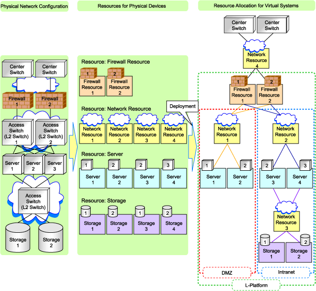
When defining a network environment, the physical network device configuration should be designed considering the virtual systems that will actually be provided to the users.
Resource Orchestrator Networks
Resource Orchestrator networks are categorized into the following three types:
Network for the Admin LAN
The admin LAN is the network used by admin servers to communicate with agents on managed servers and other managed devices (network and storage devices) for performing installation, operation, and maintenance.
Network for the Public LAN
The public LAN is the network used by managed servers and managed network devices (firewalls and L2 switches) to provide services over internal or external networks (such as intranets or the Internet).
Network for the iSCSI LAN
The iSCSI LAN is the network designed for communication between managed servers and storage devices.
For keeping operations secure, it is recommended to physically configure each network separately.
The maximum value of the subnet mask of the network that Resource Orchestrator support is 255.255.255.255(32bit mask). The minimum value is 255.255.0.0(16bit mask). However, 255.255.255.254 is not supported.
Information
The admin LAN and iSCSI LAN are the networks that only infrastructure administrators need to be concerned about in normal operation.
Figure 4.1 Network Environment Example
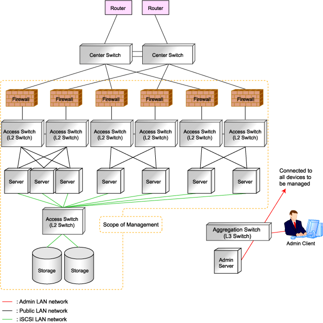
Managed devices (servers, storage units, and network devices), the admin server, and the admin client are connected to the admin LAN.
An admin LAN can be divided into multiple admin LANs. Using this function, communication among tenants on physical L-Servers performed through an admin LAN can be prevented.
When using multi-tenant functions, prepare a separate admin LAN for each tenant, and configure the admin LAN for each tenant for network pools.
This improves the security of the network.
Information Necessary for Design
When designing an admin LAN, the following information needs to be defined beforehand:
Estimate the number of tenants.
Define the number of VLAN IDs for use on the admin LAN.
As the upper limit of the number of VLAN IDs varies depending on the device, when using devices that connect with both the admin and public LANs, ensure that the number does not exceed the maximum.
Define the VLAN ID range for use on the admin LAN.
As available VLAN ID range varies depending on the device, when using the devices that connect with both the admin and public LANs, ensure that ranges do not overlap.
Define the IP address range of the admin LAN.
Decide whether to configure admin route redundancy.
Admin LAN for Servers
For each server, choose the network interfaces to use for the following purposes.
Decide the network interfaces assigned to the admin LAN.
The number of network interfaces required for the admin server and managed servers can be determined as follows.
For a non-redundant configuration: one network interface
For a redundant configuration: two network interfaces
If HBA address rename is used, two network interfaces (named NIC1 and NIC2) are required regardless of network redundancy.
For details, refer to "Required Network Configuration when Using HBA address rename".
For PRIMERGY Managed Servers
For a non-redundant configuration
NIC1 (Index1)
For a redundant configuration, or when using HBA address rename
NIC1 (Index1) and NIC2 (Index2)
The NICs above used by managed servers are the default values, and they can be changed when registering managed servers.
For details, refer to "2.4 When using Blade Servers" and "2.5 When using Rack Mount and Tower Servers" in the "User's Guide for Infrastructure Administrators (Resource Management) CE".
For PRIMEQUEST Managed Servers
For a non-redundant configuration
The smallest NIC number of the GSPB allocated to a partition
For a redundant configuration, or when using HBA address rename
The smallest and the second smallest NIC number of the GSPB allocated to a partition
For Rack Mount or Tower Managed Servers
Check the alignment sequence and number of NICs on the back of rack mount or tower servers, and then decide the numbers of NICs specified for the admin LAN using consecutive numbers starting with 1 (such as 1, 2,...).
For a non-redundant configuration
NIC 1
For a redundant configuration
NIC 1 and NIC 2
Choose the following settings to fit the system environment.
Decide whether to use Admin LAN redundancy.
Perform the redundancy of the admin LAN as below.
For physical L-Servers, use Intel PROSet, PRIMECLUSTER GLS, or Linux bonding.
For VM hosts, perform redundancy according to the server virtualization software used.
Decide the network configuration for LAN switch blades.
Admin LAN for Network Devices
Choose the LAN ports of the network devices (firewalls, L2 switches, and L3 switches) to be used.
Figure 4.2 Admin LAN Connection Example
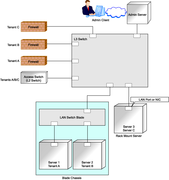
See
When the manager is Windows, and the admin LAN is operated among multiple subnets, install DHCP servers referring to "2.1.2 Installation [Windows]" in the "Installation Guide CE".
Note
Do not place DHCP servers between the manager and managed servers.
For the admin server, only a single IP address can be used on the admin LAN.
When the manager OS is Linux, DHCP servers cannot be installed.
A network address that was set when installing the manager has been registered as an admin LAN network resource.
Change the admin LAN network resource specifications, and register the IP address of a device that is not managed by Resource Orchestrator as an IP address to exclude from allocation.
If the IP address is not registered, it may conflict with the IP addresses of devices that are not managed by Resource Orchestrator.
When using blade servers, connecting the management blade to a LAN switch blade will make the management blade inaccessible in the event of a LAN switch blade failure. Therefore, it is recommended that the management blade be connected to the admin LAN using a LAN switch outside the chassis.
When performing I/O virtualization using HBA address rename, if specifying a 10Gbps expansion card (NIC) for the admin LAN, backup and restore, and cloning cannot be used.
Do not place a DHCP server or a PXE server on the admin LAN.
Do not configure multiple IP addresses for network interfaces used on the admin LAN.
When the same cloning image is deployed to multiple servers, IGMP snooping should be enabled on admin LAN switches. If IGMP snooping is not enabled, transfer performance may deteriorate in the following cases:
When ports with different speeds co-exist in the same network
When multiple image operations are being executed simultaneously
For PRIMERGY BX900/BX400 LAN switch blades operating in IBP mode, the admin LAN should not be included in the ServiceLAN or the ServiceVLAN group configuration.
Safer Communication
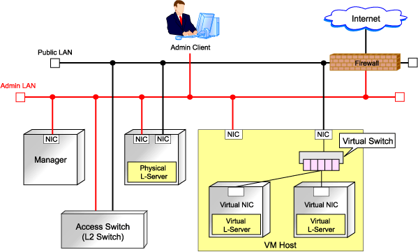
For environments where virtual L-Servers and the admin server (manager) communicate, it is recommended to perform the following configuration to improve security:
Place a firewall between the public LAN used by the virtual L-Servers and the admin LAN.
Installing firewalls or configuring OS firewalls according to the description in "Appendix A Port List" enables secure operation of the admin LAN.
In Resource Orchestrator, the manager accesses agents using HTTPS communication.
Figure 4.3 Network Configuration Example
Required Network Configuration when Using HBA address rename
At startup a managed server set with HBA address rename needs to communicate with the Resource Orchestrator manager. To enable startup of managed servers even when the manager is stopped, Resource Orchestrator should be set according to one of the following configurations.
Manager cluster configuration with admin LAN redundancy using the redundant line control function of PRIMECLUSTER GLS or Intel PROSet
For details, refer to "Appendix B Manager Cluster Operation Settings and Deletion" in the "Installation Guide CE".
Dedicated HBA address rename server
This section describes the network configuration that is required for an environment with a dedicated HBA address rename server.
For details about the HBA address rename setup service, refer to "8.2.1 Settings for the HBA address rename Setup Service".
This service must be on the same admin LAN as the admin server. Do not start more than one instance of this service.
This service uses NIC2 (Index2).
Connect NIC2 of the managed server to the admin LAN.
NIC2 is the default value, and it can be changed when registering managed servers.
For details, refer to "2.4 When using Blade Servers" in the "User's Guide for Infrastructure Administrators (Resource Management) CE".
This service periodically obtains information about managed servers from the admin server and operates using this information. For this reason, it should be installed on a server that can be left active all the time.
There must be two LAN cables between LAN switches (cascade connection) on the admin server and on the managed server.
[Linux]
Use eth0, for the network interface for this service to communicate with the admin server.
Connect the eth0 NIC to the admin LAN.
Note
The HBA address rename setup service cannot operate on the same server as ServerView Deployment Manager, or on a server where any other DHCP or PXE service is running.
The following diagram shows an example of how the HBA address rename setup service can be configured.
Figure 4.4 Sample Configuration Showing the HBA address rename Setup Service (with PRIMERGY BX600)
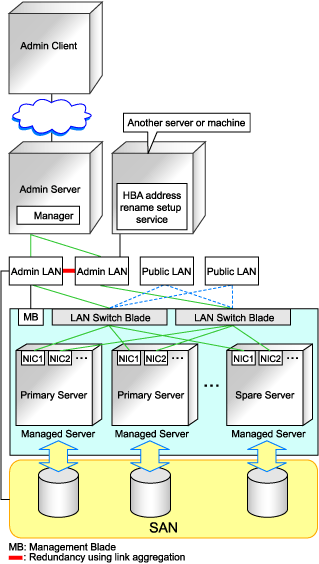
Connections between switches on the admin LAN can be made redundant using link aggregation.
Connect NIC2 (Index2) to the admin LAN (when it is the default).
Configure the HBA address rename setup service on a server connected to the admin LAN. This server must be different from the admin server.
Ensure that the server or personal computer that is used to operate the HBA address rename setup service is always on when the managed servers are active.
Design virtual systems for users.
Information Necessary for Design
When designing virtual systems, the following information needs to be defined beforehand:
Define the required resources.
Decide whether to use firewalls.
If security must be maintained for each virtual system, deploy firewalls.
Firewalls should also be deployed when using a hierarchical configuration that establishes an intranet connected with a DMZ.
Choose the server type (physical L-Server or virtual L-Server).
Decide whether to use iSCSI. (Storage)
Define the communication route configuration.
It is normal to use a redundant configuration for communication routes.
Define the assumed communication performance (throughput).
Define the assumed communication performance for each system.
Figure 4.5 Example of Virtual System Configuration Elements
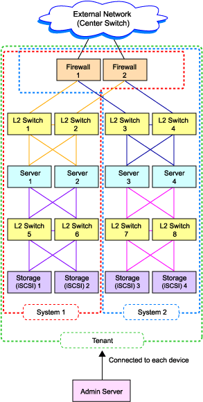
Figure 4.6 Example of Overall Configuration of a Virtual System (A Collective of Virtual System Configuration Elements)
Managed devices (server machines and network devices) are connected using the public LAN.
Managed devices (server machines and storage units) are connected using the iSCSI LAN.
Design of an iSCSI LAN is required to connect the iSCSI-enabled storage devices and servers to which physical L-Servers will be deployed.
Information Necessary for Designing a Public LAN
When designing a public LAN, the following information needs to be defined beforehand:
Estimate the number of required devices (servers and network devices).
Define the required devices based on the designed virtual system.
The number of required devices should be estimated based on the following information:
Performance requirements assumed during designing of the virtual system
The number of planned tenants defined during designing of the admin LAN
Specifications of devices to be used
Estimate the specifications (including supported functions) required for the devices.
Define the number of VLAN IDs for use on the public LAN.
As the upper limit of the number of VLAN IDs varies depending on the device, when using devices that connect with both the admin and public LANs, ensure that the number does not exceed the maximum.
Define the VLAN ID range for use on the public LAN.
As available VLAN ID range varies depending on the device, when using the devices that connect with both the admin and public LANs, ensure that ranges do not overlap.
Define the IP address range of the public LAN.
Decide whether to configure communication route redundancy.
Whether to configure communication route redundancy should be decided based on the designed virtual system.
Define the LAN ports or NICs to use.
Define one of the following:
For network devices, LAN ports other than the ones assigned to the admin LAN.
For servers, NIC ports other than the ones assigned to the admin LAN.
When planning to use a rack mount server or tower server as a physical L-Server, define the following information:
The NIC number of the rack mount server or tower server
Check the alignment sequence and number of NICs on the back of the rack mount or tower servers, and then choose the numbers of NICs to be specified when creating a physical L-Server, by consecutive numbers starting with 1 (such as 1, 2,...).
As the admin LAN uses small NIC numbers ("1" for non-redundant admin LANs or "1-2" for redundant LANs), ensure NICs with larger numbers are used.
Information
For blade servers, depending on the model of LAN switch blade used in the same chassis, certain network interfaces may not be available.
In this case, add expansion NICs and a LAN switch blade, or share the NIC used for the admin LAN.
All network interfaces shared between the admin LAN and the public LAN for managed servers should be configured with tagged VLAN IDs.
The NICs that are unavailable depend on the combination of the mounted LAN switch blade and blade server. For details, refer to the manual of the LAN switch blade and blade server.
Information Necessary for Designing an iSCSI LAN
When designing an iSCSI LAN, the following information needs to be defined beforehand:
Define a NIC on the server used for an iSCSI LAN.
Both single and multi-path configurations are available.
For each tenant, define a network address and a VLAN ID for use on the iSCSI LAN.
Define whether to connect external switches between ETERNUS storage and LAN Switch Blades, or NetApp storage and LAN switch blades.
Define whether to use multi-tenant functions on ETERNUS storage or NetApp storage.
Define an IQN to be used for the NIC of the server.
Decide a network address to be used for the port of the storage.
Define an IQN to be used for the port of the storage.
Define the use of authentication on iSCSI communication. When using authentication, define the authentication information.
Determine the physical network configuration by defining devices necessary for the public LAN and iSCSI LAN that meet the requirements for the designed virtual system.
A sample image of virtual systems and the corresponding physical network configuration is shown below:
Figure 4.7 Sample Image of Virtual Systems and the Corresponding Physical Network Configuration
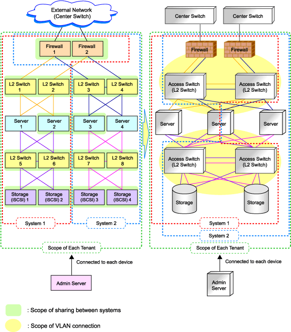
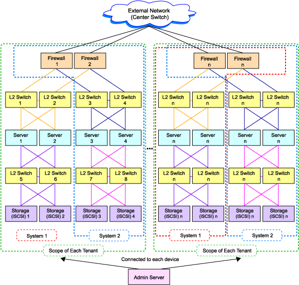
By defining how many virtual systems should be configured for each tenant and how many tenants are to be prepared, the required number of devices can be determined, making the overall configuration clear.
An example of the overall configuration of the physical system is shown below:
Figure 4.8 Example of Overall Physical Network Configuration
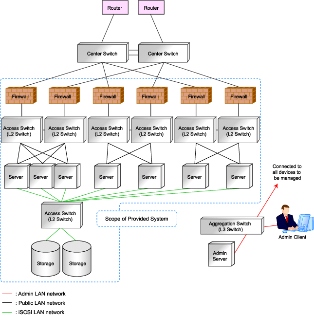
This section explains the relationship between the defined physical system and the resources managed by Resource Orchestrator.
Using Resource Orchestrator, you can provide users with virtual systems and also operate those virtual systems. Therefore, it is necessary to understand the relationship between physical systems and the resources configuring the virtual systems in advance.
Depending on how the physical devices are used in the virtual system, physical devices and resources can be in "one-to-one" or "one-to-n" relationships.
The relationship between physical networks and resources is shown below, using "Figure 4.8 Example of Overall Physical Network Configuration" as an example.
Figure 4.9 Relationship between Physical Network Configuration and Resources
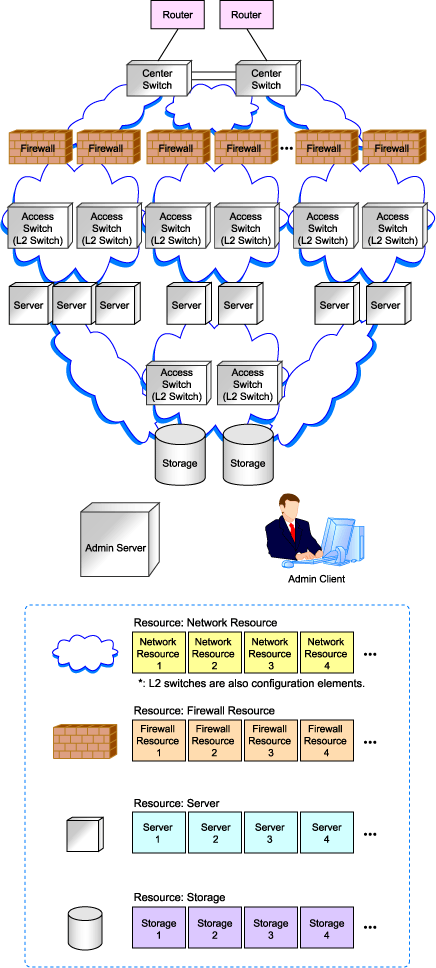
The following figure shows a sample image when physical devices and resources are allocated for a single virtual system (L-Platform).
In this sample image, resources are allocated for firewalls and L2 switches on a one-to-one basis, while resources are allocated for servers and storage devices on a one-to-n basis.
Resource Orchestrator manages L2 switches as network devices. However, when allocated to a virtual system, L2 switches are not displayed on the virtual system because they are included as network resource components.
Figure 4.10 Virtual System and Resource Allocation Example
