

| PRIMECLUSTER Global Link Services Configuration and Administration Guide: Redundant Line Control Function 4.1 (for Solaris(TM) Operating System) |
|
Contents
Index
|
| Chapter 5 GLS operation on cluster systems | > 5.1 Outline of Cluster System Support | > 5.1.1 Active Standby | > 5.1.1.2 Switching |
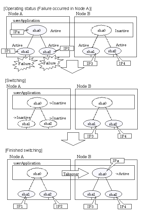
Figure 5.11 illustrates switching behavior of GS/SURE linkage mode.
In the figure below, a takeover virtual interface (sha0) is activated in the operating node. When switching occurs due to a failure, deactivate takeover virtual interface (sha0) and the virtual interfaces (sha1, sha2) in node A. Then, GS/SURE linkage mode activates the virtual interfaces (sha1, sha2). On standby node B, it activates the takeover virtual interface (sha0), which bundles the virtual interfaces (sha1, sha2).
|
Contents
Index
|