
| PRIMECLUSTER Global Link Services Configuration and Administration Guide: Redundant Line Control Function 4.1 (for Solaris(TM) Operating System) |
Contents
Index
 
|
| Chapter 5 GLS operation on cluster systems | > 5.1 Outline of Cluster System Support | > 5.1.1 Active Standby | > 5.1.1.2 Switching |
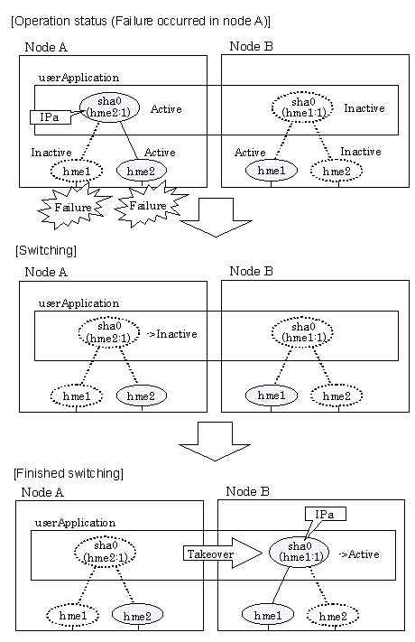
Figure 5.8 illustrates switching behavior of NIC switching mode (logical IP address takeover function).
In the following figure, the takeover virtual IP address (IPa) in the operating node A is allocated to the logical interface (hme2.1) for the secondary interface. Once IPa is allocated, the logical interface (hme2.1) for the secondary interface turns into activate state.
When switching the node due to failure in the transfer routes, NIC switching mode inactivates the logical virtual interface which has allocated the takeover IP address (IPa) in the operating node A. Then it allocates the takeover IP address to the primary interface (hme1) and finally activates the logical interface (hme1:1).

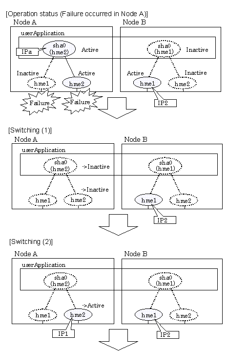
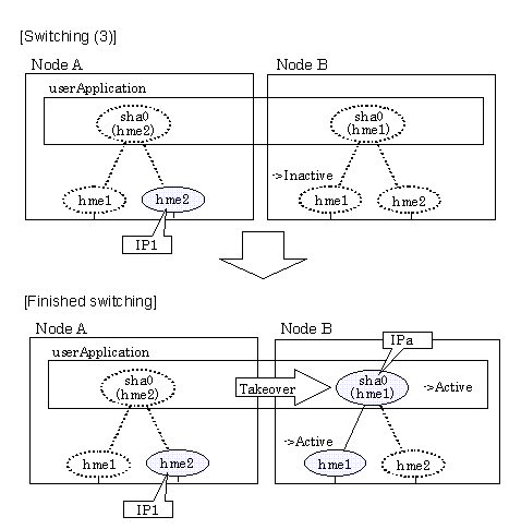
Figure 5.9 illustrates switching behavior of NIC switching mode (takeover physical IP address I).
In the following figure, the takeover virtual IP address (IPa) in the operating node A is allocated to the secondary interface. Once IPa is allocated it turns into activate state.
When switching the node due to a failure in the transfer routes, temporally inactivate the primary interface (hme1), which has been active in the standby node B. Then it allocates the takeover IP address (IPa) to activate the primary interface (hme1). Once the primary interface activates, different IP address is allocated to the secondary interface (hme2) by means of inactivating hme2.


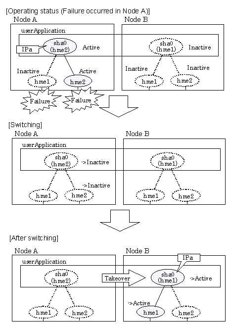
Figure 5.10 illustrates switching behavior of NIC switching mode (takeover physical IP address II).
In the following figure, the takeover IP address (IPa) in the operating node A is allocated to the secondary interface. Once IPa is allocated it turns into activate state.
When switching the node because of a failure in the transfer path, the standby node B turns to be active by allocating the takeover IP address (IPa) to the primary interface (hme1). After the IP address is successfully passed over to the standby node, the secondary interface (hme2), which previously owned the takeover IP address (IPa) in node A becomes inactive.

Contents
Index
 
|