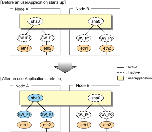
By starting userApplication, the takeover virtual interface (sha0) and the gateway addresses (GW_IP1, GW_IP2) on the operating node become active allowing communication using the takeover virtual IP address. During normal operation, the GS linkage mode uses the takeover virtual interface on the operating node to communicate with the remote system.
Figure 5.20 Startup behavior of GS linkage mode shows startup behavior of the GS linkage mode.
Figure 5.20 Startup behavior of GS linkage mode

Note
Activate the gateway addresses (GW_IP1, GW_IP2) only when they are connected to GS via a router.
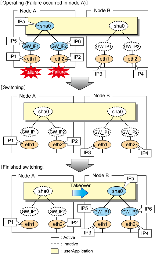
Figure 5.21 Switching behavior of GS linkage mode illustrates switching behavior of GS linkage mode.
In the figure below, a takeover virtual interface (sha0) is activated in the operating node. When switching occurs due to a failure, deactivate takeover virtual interface (sha0) and the physical interfaces (eth1:X,eth2:X) in node A. On standby node B, it activates the takeover virtual interface (sha0), which bundles the physical interfaces (eth1, eth2).
Figure 5.21 Switching behavior of GS linkage mode

Note
Activate or deactivate the gateway addresses (GW_IP1, GW_IP2) only when they are connected to GS via a router.
The procedure for performing fail-back is the same as in Fast switching mode. For details, see "5.4.1.3 Fail-back".
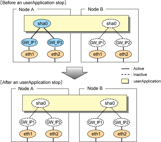
Figure 5.22 Stopping process of GS linkage mode illustrates stopping behavior of userApplication.
Figure 5.22 Stopping process of GS linkage mode

Note
Activate or deactivate the gateway addresses (GW_IP1, GW_IP2) only when they are connected to GS via a router.