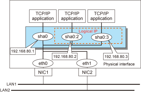
It is possible to define several logical interfaces on a single virtual interface. They are called logical virtual interfaces. By using this function, various IP addresses can be used for each application.
Note
Virtual IP addresses allocated to the logical virtual interfaces must be on the same subnet as the virtual interfaces.
As shown in Figure 2.27 Logical virtual interfaces being defined, when defining two logical virtual interfaces (sha0:2 and sha0:3) on a virtual interface sha0, you must configure the IP address of the same subnet on sha0, sha0:2, and sha0:3.
Information
When configuring logical virtual interfaces (two logical virtual interfaces, sha0:2 and sha0:3, in Figure 2.27 Logical virtual interfaces being defined) on a virtual interface sha0, the logical virtual interfaces are displayed as the secondary addresses of sha0 by the ip command.
An example of a display is as follows:
# ip addr show sha0
N: sha0: <BROADCAST,MULTICAST,UP,LOWER_UP> mtu 1500 qdisc pfifo_fast state UP group default qlen 1000
    link/ether XX:XX:XX:XX:XX:XX brd ff:ff:ff:ff:ff:ff
    inet 192.168.80.1/24 brd 192.168.80.255 scope global sha0
       valid_lft forever preferred_lft forever
    inet 192.168.80.2/24 brd 192.168.80.255 scope global secondary sha0
       valid_lft forever preferred_lft forever
    inet 192.168.80.3/24 brd 192.168.80.255 scope global secondary sha0
       valid_lft forever preferred_lft forever
Figure 2.27 Logical virtual interfaces being defined

The total number of interfaces can be created as a logical virtual interface is 63 (from 2 to 64). The logical virtual interfaces greater than 65 will be used as takeover virtual interface upon Cluster configuration.
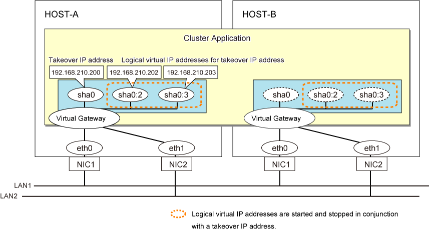
For GS linkage mode in a cluster configuration, you can take over a virtual IP address which belongs to the same network between clusters by using the logical virtual interface.
Figure 2.28 Logical virtual interfaces being defined (GS linkage mode in a cluster configuration)

Note
This function is only available for the Fast switching mode, the Virtual NIC mode, and the GS linkage mode.
For the NIC switching mode, if using the physical interface sharing function, it can process (a process of allocating multiple IP addresses to one physical interface) equally as this function.
For the Virtual NIC mode, set the logical virtual interfaces as the secondary addresses of /etc/sysconfig/network-scripts/ifcfg-sha0.
You do not need to create the OS definition file (/etc/sysconfig/network-scripts/ifcfg-sha0:2).