The redundant line control function provides a high-reliability communication infrastructure that supports continuous transmission in the event of a network path or card failure by making transmission routes redundant with multiple NIC (Network Interface Cards).
The redundant line control function provides the following four network control methods:
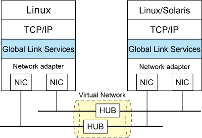
In Fast switching mode, a redundant transmission route between Linux servers or Solaris servers in the same network is used so that the total amount of data transferred can be increased, and that the data communication can be continued even if the transmission route fails. It also enables higher levels of throughput through redundant transmission routes. GLS performs early failure detection, so when one transmission route fails, the failed route will be cut off then the system will be operated on a reduced scale. The compatible hosts are PRIMEQUEST, PRIMERGY, SPARC M10, SPARC Enterprise, PRIMEPOWER, and other systems where GLS's Fast switching mode is running.
Note that fast switching mode cannot be used to communicate with hosts on the other networks beyond the router.
Moreover, you can use a transfer path that is not multiplexed. For details, refer to "2.2.4 Configuring single physical interface".
Figure 1.1 Fast switching mode

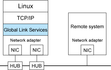
In NIC switching mode, redundant NICs (LAN cards) are connected to each other on the same network and used exclusively. If one transmission route fails, ongoing communications will be switched to the other transmission route. There are no restrictions on remote systems to communicate with.
Note that NIC switching mode can be used to communicate with any hosts on the other networks beyond the router.
Moreover, you can use NIC that is not multiplexed. For details, refer to "2.2.4 Configuring single physical interface".
Figure 1.2 NIC switching mode

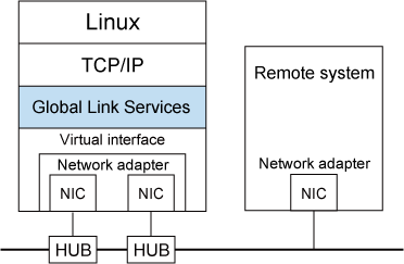
In Virtual NIC mode, communication is performed by generating a virtual interface so that multiple physical NICs (LAN cards) can be seen as one logical NIC. In this mode, switching transfer routes is controlled by exclusive use of redundant NICs. If one transmission route fails, ongoing communications will be switched to the other transmission route. There are no restrictions on remote systems to communicate with.
Note that Virtual NIC mode can be used to communicate with any hosts on the other networks beyond the router.
Moreover, you can use NIC that is not multiplexed. For details, refer to "2.2.4 Configuring single physical interface".
Figure 1.3 Virtual NIC mode

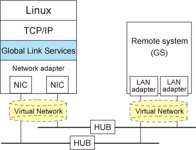
GS linkage mode enables the system to control lines by using a Fujitsu method for high-reliability communication between the system and Global Server. In this mode, duplicated lines are used concurrently. During normal operation, lines are automatically assigned to each TCP connection for communication. In the event of a fault, the system disconnects the faulty line and operates on a reduced scale by moving the TCP connection to the normal line. The compatible hosts are Global Server and PRIMEQUEST or PRIMERGY where GLS's GS linkage mode is running.
Note that GS linkage mode can be used to communicate with any hosts on other networks connected to the router. You can use NIC that is not multiplexed. For details, see "2.2.4 Configuring single physical interface". (Hereafter, GS refers to Global Server).
Figure 1.4 GS linkage mode
