The following examples show various network configurations and what their topology tables would look like when the topology table is displayed in the CF Wizard on a totally unconfigured cluster. For simplicity, the check boxes are omitted.
Example 1
In this example, there is a three-node cluster with three full interconnects.
Figure 6.1 A three-node cluster with three full interconnects
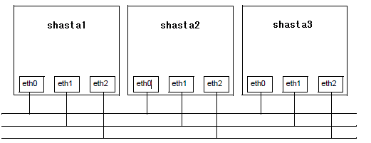
The resulting topology table for the above figure is shown in the following table.
SHASTAS | Full interconnects | ||
|---|---|---|---|
Int 1 | Int 2 | Int 3 | |
shasta1 | eth0 | eth1 | eth2 |
shasta2 | eth0 | eth1 | eth2 |
shasta3 | eth0 | eth1 | eth2 |
Since there are no partial interconnects or unconnected devices, those columns are omitted from the topology table.
Example 2
In this example, shasta1's Ethernet connection for eth1 has been broken.
Figure 6.2 Broken ethernet connection for eth1 on shasta1
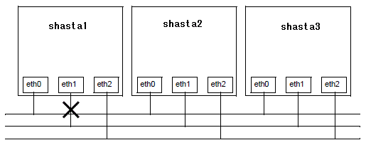
The resulting topology table for Figure 63 is shown in Table 7.
SHASTAS | Full interconnects | Partial interconnects | Unconnected devices | |
|---|---|---|---|---|
Int 1 | Int 2 | Int 3 | ||
shasta1 | eth0 | eth2 | missing | eth1 |
shasta2 | eth0 | eth2 | eth1 | |
shasta3 | eth0 | eth2 | eth1 | |
In the "Table 6.4 Topology table with broken Ethernet connection," eth1 for shasta1 now shows up as an unconnected device. Since one of the interconnects is missing a device for shasta1, the Partial Interconnect column now shows up. Note that the relationship between interconnect numbering and the devices has changed between the "Table 6.3 Topology table for 3 full interconnects" and the "Table 6.4 Topology table with broken Ethernet connection". In "Table 6.3 Topology table for 3 full interconnects," for example, all eth1 devices were on Int 2. In the "Table 6.4 Topology table with broken Ethernet connection," the eth1 devices for Nodes B and C are now on the partial interconnect Int 3. This change in numbering illustrates the fact that the numbers have no real significance beyond the topology.
Example 3
This example shows a cluster with severe networking or cabling problems in which no full interconnects are found.
Figure 6.3 Cluster with no full interconnects
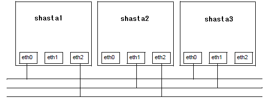
The resulting topology table for the above figure is shown in the blow table.
SHASTAS | Partial interconnects | Unconnected devices | ||
|---|---|---|---|---|
Int 1 | Int 2 | Int 3 | ||
shasta1 | eth0 | missing | eth2 | eth1 |
shasta2 | missing | eth1 | eth2 | eth0 |
shasta3 | eth0 | eth1 | missing | eth2 |
In this table, the full interconnects column is omitted since there are none. Note that if this configuration were present in the CF Wizard, the wizard would not allow you to do configuration. The wizard requires that at least one full interconnect must be present.