The following example shows what the Web-Based Admin View and Cluster Admin screens would look like when creating a two-node cluster. The nodes involved are named shasta1 and shasta2, and the cluster name is SHASTAS.
This example assumes that the Web-Based Admin View configuration has already been done. shasta1 is assumed to be configured as the primary management server for Web-Based Admin View, and shasta2 is the secondary management server.
Start the Web-Based Admin View screen from the shortcut of the Java application (PRIMECLUSTER Web-Based Admin View Startup).
After a few moments, a login pop-up appears asking for a user name and password (similar to the screen below).
Figure 1.2 Login pop-up
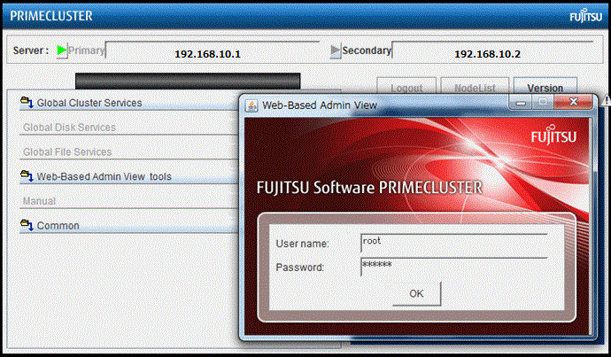
Since you will be running the Cluster Admin CF Wizard, which does configuration work, you will need a privileged user ID such as root. There are three possible categories of users with sufficient privilege:
The user root
You can enter root for the user name and root's password on shasta1. The user root is always given the maximum privilege in Web-Based Admin View and Cluster Admin.
A user in group clroot
You can enter the user name and password for a user on shasta1 who is part of the UNIX group clroot. This user will have maximum privilege in Cluster Admin, but will be restricted in what Web-Based Admin View functions they can perform. This should be fine for CF configuration tasks.
A user in group wvroot
You can enter the user name and password for a user on shasta1 who is part of the UNIX group wvroot. Users in wvroot have maximum Web-Based Admin View privileges and are also granted maximum Cluster Admin privileges.
For further details on Web-Based Admin View and Cluster Admin privilege levels, refer to "4.3.1 Assigning Users to Manage the Cluster" in "PRIMECLUSTER Installation and Administration Guide."
After clicking on the OK button, the top menu appears. Click on the button labeled Global Cluster Services.
Figure 1.3 Main Web-Based Admin View window after login
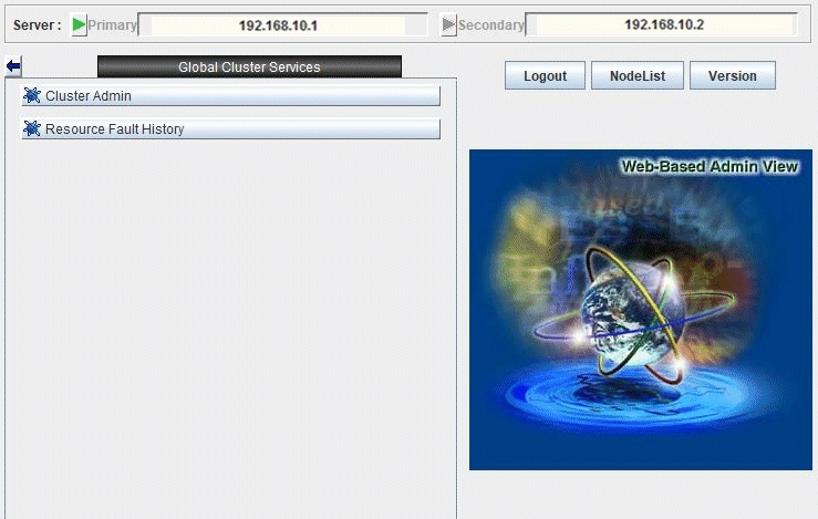
The Cluster Admin selection window appears.
Figure 1.4 Global Cluster Services window in Web-Based Admin View
Click on the button labeled Cluster Admin to launch the Cluster Admin GUI.
The Choose a node for initial connection window appears.
Figure 1.5 Initial connection pop-up
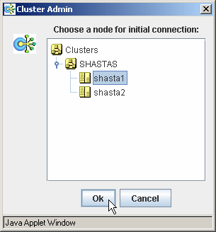
The Choose a node for initial connection window lists the nodes that are known to the Web-Based Admin View management station. If you select a node where CF has not yet been configured, then Cluster Admin will let you run the CF Wizard on that node.
In this example, neither shasta1 nor shasta2 have had CF configured, so either would be acceptable as a choice. In Figure 1.6, shasta1 is selected. Clicking on the OK button causes the main Cluster Admin GUI to appear. Since CF is not configured on shasta1, a window similar to the following figure appears.
When cancelling the startup of the Cluster Admin GUI, click the <Cancel> button in the initial connection pop-up screen.
Figure 1.6 CF is unconfigured and unloaded
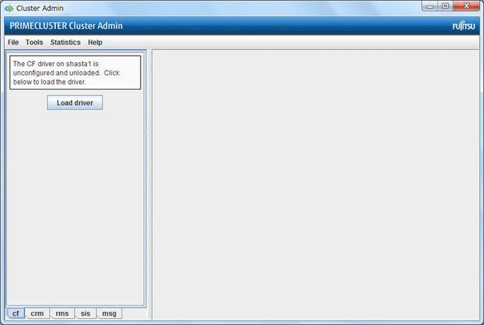
Click on the Load driver button to load the CF driver.
A window indicating that CF is loaded but not configured appears.
Figure 1.7 CF loaded but not configured
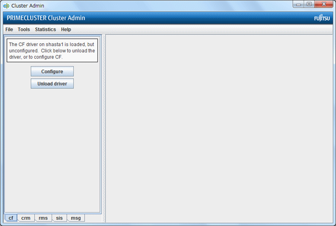
Click on the Configure button to bring up the CF Wizard. The CF Wizard scans for existing clusters.
After the CF Wizard finishes looking for clusters, a window similar to Figure 1.9 appears.
Figure 1.8 Creating or joining a cluster
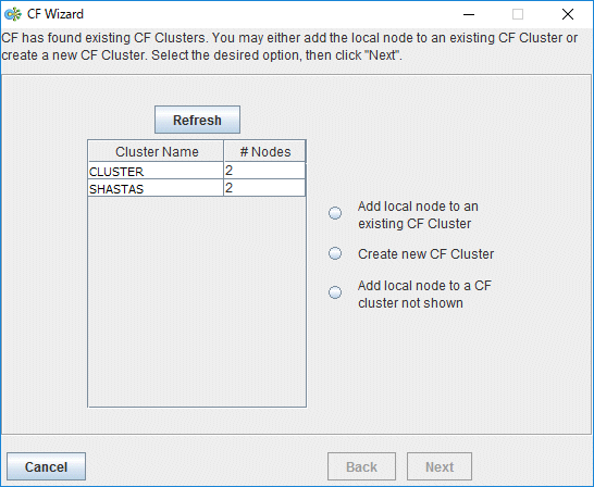
This window lets you decide if you want to join an existing cluster or create a new one.
A pure CF over IP cluster will not show up in the Cluster Name column. To join a CF over IP cluster, select the Add local node to a CF cluster not shown radio button and click Next.
Figure 1.9 Adding a local node to a CF cluster not shown
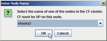
Enter the node name of the CF cluster that you want to join. Click OK to proceed. After scanning the node and retrieving the existing cluster's details, the CF wizard takes you to the window for joining an existing cluster.
To create a new cluster as shown in "Figure 1.8 Creating or joining a cluster", make sure that the [Create new CF Cluster] radio button is selected. Then, click <Next>.
The window for creating a new cluster or for joining an existing cluster appears, depending on your previous selection.
The following figure shows the window for creating a new cluster. The window for joining an existing cluster has almost the same configuration as the window for creating a new cluster except that the cluster name cannot be changed.
Note
Make sure to select [Create new CF Cluster] in the following environments:
For a cloud environment
For an RHOSP environment
When configuring an interconnect between cluster nodes with different network segments
When a device that only supports IP exists in the route tracking of the interconnect
Figure 1.10 Selecting cluster nodes and the cluster name
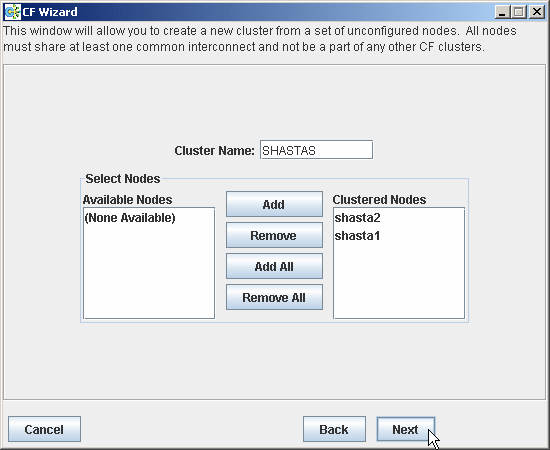
This window lets you chose the cluster name and also determine what nodes will be in the cluster. In the example above, we have chosen SHASTAS for the cluster name.
Below the cluster name are two boxes. The one on the right, under the label Clustered Nodes, contains all the nodes that you want to become part of this CF cluster. The box on the left, under the label Available Nodes, contains all the other nodes known to the Web-Based Admin View management server. You should select nodes in the left box and move them to the right box using the Add or Add All button. If you want all of the nodes in the left box to be part of the CF cluster, then just click on the Add All button.
If you get to this window and you do not see all of the nodes that you want to be part of this cluster, then there is a very good chance that you have not configured Web-Based Admin View properly. When Web-Based Admin View is initially installed on the nodes in a potential cluster, it configures each node as if it were a primary management server independent of every other node. If no additional Web-Based Admin View configuration were done, and you started up Cluster Admin on such a node, then Figure 1.11 would show only a single node in the right-hand box and no additional nodes on the left-hand side. If you see this, then it is a clear indication that proper Web-Based Admin View configuration has not been done.
Refer to "4.3 Preparations for Starting the Web-Based Admin View Screen" in "PRIMECLUSTER Installation and Administration Guide."
After you have chosen a cluster name and selected the nodes to be in the CF cluster, click on the Next button.
The CF Wizard then loads CF on all the selected nodes and does CF pings to determine the network topology. While this activity is going on, a window similar to Figure 1.12 appears.
Figure 1.11 CF loads and pings
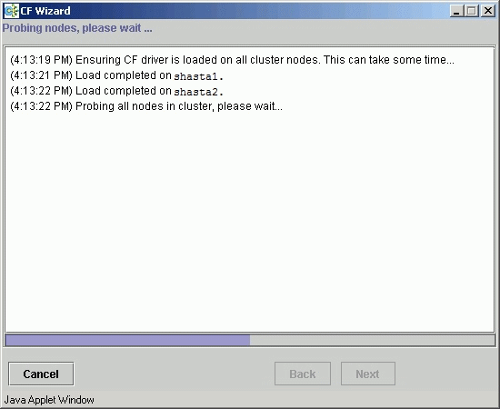
Usually, loading the CF driver is a relatively quick process. However, on some systems which use large disk arrays, the first CF load can take several minutes.
The window that allows you to edit the CF node names for each node appears. By default, the CF node names, which are shown in the right-hand column, are the same as the Web-Based Admin View names which are shown in the left-hand column.
Figure 1.12 Edit CF node names
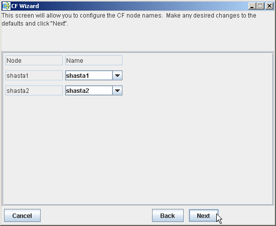
Make any changes to the CF node name and click Next.
After the CF Wizard has finished the loads and the pings, the CF topology and connection table appears.
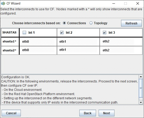
Figure 1.13 CF topology table/CF connection table
Point
Use CF over IP for the following:
For a cloud environment
For an RHOSP environment
When configuring an interconnect between cluster nodes with different network segments
When a device that only supports IP exists in the route tracking of the interconnect
When using CF over IP, uncheck all the checkboxes of the interconnects and click [Next].
Before explaining the CF topology table and the connection table in this screen, the following terms are defined:
Full interconnect - An interconnect where CF communication is possible to all the nodes in the cluster.
Partial interconnect - An interconnect where CF communication is possible between at least two nodes, but not to all the nodes. If the devices on a partial interconnect are intended for CF communications, then there is a networking or cabling problem somewhere.
Unconnected devices - These devices are potential candidates for CF configuration, but are not able to communicate with any other nodes in the cluster.
The CF Wizard determines all the full interconnects, partial interconnects, and unconnected devices in the cluster using CF pings. If there are one or more full interconnects, then it will display the connection table shown in "Figure 1.13 CF topology table/CF connection table."
Connections table
The connection table lists all full interconnects. Each column with an Int header represents a single interconnect. Each row represents the devices for the node whose name is given in the left-most column. The name of the CF cluster is given in the upper-left corner of the table.
In "Figure 1.13 CF topology table/CF connection table", for example, Int 1 has eth0 on shasta1 and shasta2 attached to it. The cluster name is SHASTA.
Note
The connections and topology tables typically show devices that are on the public network. Using devices on a public network is a security risk; therefore, in general, do not use any devices on the public network as a CF interconnect. Instead, use devices on a private network.
Although the CF Wizard may list Int 1, Int 2, and so on, it should be pointed out that this is simply a convention in the GUI. CF itself does not number interconnects. Instead, it keeps track of point-to-point routes to other nodes.
Occasionally, there may be problems setting up the networking for the cluster. Cabling errors may mean that there are no full interconnects. If you click on the button next to Topology, the CF Wizard will display all the full interconnects, partial interconnects, and unconnected devices it has found. If a particular category is not found, it is omitted. For example, in "Figure 1.13 CF topology table/CF connection table", only full interconnects are shown because no partial interconnects or unconnected devices were found on shasta1 or shasta2.
To configure CF using the connection table, click on the interconnects that have the devices that you want to use.
When you are satisfied with your choices, click on Next to go to the CF over IP configuration window.
Topology table
The topology table gives more flexibility in configuration than the connection table. In the connection table, you could only select an interconnect, and all devices on that interconnect would be configured. In the topology table, you can individually select devices.
While you can configure CF using the topology table, you may wish to take a simpler approach. If no full interconnects are found, then display the topology table to see what your networking configuration looks like to CF. Using this information, correct any cabling or networking problems that prevented the full interconnects from being found. Then go back to the CF Wizard window where the cluster name was entered and click on Next to cause the Wizard to reprove the interfaces. If you are successful, then the connection table will show the full interconnects, and you can select them. Otherwise, you can repeat the process.
The text area at the bottom of the window lists problems or warnings concerning the configuration.
When you are done, click on Next to go to the CF over IP configuration window.
CF can use either Ethernet packets or IP for its communication. The topology table and connection table discussed previously allow you to configure CF to use Ethernet packets. This is the preferred CF configuration since CF over Ethernet is significantly faster than CF over IP.
However, CF over Ethernet requires Ethernet link-level connectivity between the nodes in a cluster. In certain disaster recovery scenarios, there may only be IP connectivity between hosts. This is typically the case when the hosts are separated by large geographical distances.
Figure 1.14 CF over IP configuration window
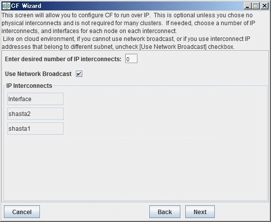
If you have already configured CF over Ethernet in the topology table or the connection table, you do not have to change any settings on this screen. Just click [Next].
Note
If the interconnection of each node has the same network segment, perform this configuration. See "- For cluster nodes placed between different network segments" when reaching between cluster nodes with different network segments.
Figure 1.15 CF over IP configuration window

Use the configuration window above to configure CF to run over the IP network.
CF over IP uses IP subnetworks in the same way that CF over Ethernet uses physical interconnects. Each IP interconnect must correspond to exactly one subnetwork. For example, suppose that your nodes had the following IP interfaces:
node     subnet1         subnet 2         subnet 3
----------------------------------------------------------------
shasta1  172.25.222.105  192.168.223.105  185.33.48.105
shasta2  172.25.222.112  192.168.223.112  185.33.48.112
Using CF over IP, you might configure one IP interconnect to use the IP addresses 192.168.223.105 and 192.168.223.112. You could configure a second IP interface using the addresses 185.33.48.105 and 185.33.48.112.
But if you need CF over IP, then set [Enter desired number of IP interconnects] to "2" (or more if desired). Up to 4 IP interconnects can be set. The Wizard will propose IP interconnects. The IP interconnects are conveniently sorted by subnetwork. If you think that a particular subnetwork is missing a node, then double check that the netmask and broadcast addresses are properly configured for all the nodes on subnetwork.
Select the subnetworks that you want to use as your IP interconnects. You should avoid using addresses on your public network. CF allows promiscuous joins without any limits, so it is best to use private subnetworks for your IP interconnects.
With this setting, CF can be configured to run over the IP interface. After entering the number of required IP interconnects, the CF Wizard will display interconnects sorted by available subnetworks, netmasks, and broadcast addresses.
All the IP addresses for all the nodes on a given IP interconnect must be on the same IP subnetwork and should have the same netmask and broadcast address.
Confirm that [Use Network Broadcast] checkbox is checked.
Choose the IP interconnects from the combo boxes on this window, and click on [Next]. The CIP Wizard windows like "Figure 1.18 CIP wizard (IPv4) window" and "Figure 1.19 CIP wizard (IPv6) window" appear.
Set [Enter desired number of IP interconnects] to at least "1."
If it is "0," click [Back] to return to the CF topology and connection table screen, and deselect the interconnects.
Deselect [Use Network Broadcast].
Select the IP address and network interface of cluster interconnect in interconnect, and click [Next].
Figure 1.16 CF over IP configuration window
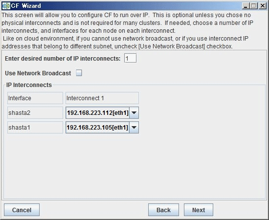
Make sure that [Enter desired number of IP interconnects] is "1."
If it is "0," click [Back] to return to the CF topology and connection table screen, and deselect the interconnects.
Deselect [Use Network Broadcast].
Select the IP address and network interface ("192.168.223.105 [eth1]" for shasta1, "192.168.223.112 [eth1]" for shasta2) of cluster interconnect in interconnect1, and click [Next].
Figure 1.17 CF over IP configuration window
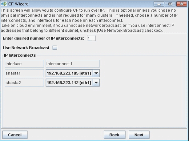
Figure 1.18 CIP wizard (IPv4) window
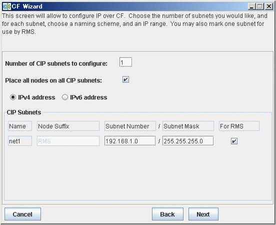
Figure 1.19 CIP wizard (IPv6) window
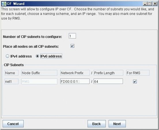
This window allows you to configure CIP. You can enter a number in the box after Number of CIP subnets to configure to set the number of CIP subnets to configure. The maximum number of CIP subnets is 8.
For each defined subnet, the CIP Wizard configures a CIP interface on each node defined in the CF cluster.
Set either IPv4 or IPv6 as the IP address to set to the CIP interface.
By selecting either of the [IPv4 address] or [IPv6 address] radio button, you can switch "Figure 1.18 CIP wizard (IPv4) window" and "Figure 1.19 CIP wizard (IPv6) window".
When using IPv4 for CIP interface
The following values are assigned for CIP interface:
The IP address will be a unique IP number on the subnet specified in the Subnet Number field. The node portions of the address start at 1 and are incremented by 1 for each additional node.
The CIP Wizard will automatically fill in a default value for the Subnet Number filed for each CIP subnetwork requested. The default values are taken from the private IP address range specified by RFC 1918. Note that the values entered in the Subnet Number field have 0 for their node portion even though the CIP Wizard starts the numbering at 1 when it assigns the actual node IP addresses.
The IP name of the interface will be of the form cfnameSuffix where cfname is the name of a node from the CF Wizard, and the Suffix is specified in the field Node Suffix. If the checkbox For RMS is selected, then the Node Suffix will be set to RMS and will not be editable. If you are using RMS, one CIP network must be configured for RMS.
The Subnet Mask will be the value specified.
In "Figure 1.18 CIP wizard (IPv4) window", the system administrator has selected 1 CIP network. The For RMS checkbox is selected, so the RMS suffix will be used. Default values for the Subnet Number and Subnet Mask are also selected. The nodes defined in the CF cluster are shasta1 and shasta2. This will result in the following configuration:
On shasta1, a CIP interface will be configured with the following:
CIP nodename: shasta1RMS
IP address: 192.168.1.1
Subnet Mask: 255.255.255.0
On shasta2, a CIP interface will be configured with the following:
CIP nodename: shasta2RMS
IP address: 192.168.1.2
Subnet Mask: 255.255.255.0
When using IPv6 for CIP interface
The following values are assigned for CIP interface:
The IP address will be a unique IP number on the network prefix specified in the Prefix field. Interface ID of the address start at 1 and are incremented by 1 for each additional node.
The CIP Wizard will automatically fill in a default value for the Prefix field for each CIP subnetwork requested. The default values are taken from the Unique Local Unicast Address range specified by RFC 4193. Note that the values entered in the Prefix field have 0 for their interface ID portion even though the CIP Wizard starts the numbering at 1 when it assigns the actual node IP addresses.
The IP name of the interface is represented in cfnameSuffix format.
cfname is the name of a node given by the CF Wizard
Suffix is specified in the field Node Suffix.
If the checkbox For RMS is selected, then the Node Suffix will be set to RMS and will not be editable. If you are using RMS, one CIP network must be configured for RMS.
The Prefix Length will be the value specified.
In "Figure 1.19 CIP wizard (IPv6) window", the system administrator has selected 1 CIP network. The For RMS checkbox is selected, so the RMS suffix will be used. Default values for the Prefix and Prefix Length are also selected. The nodes defined in the CF cluster are shasta1 and shasta2. This will result in the following configuration:
On shasta1, a CIP interface will be configured with the following:
CIP nodename: shasta1RMS
IPv6 address: FD00:0:0:1::1
Prefix Length: 64
On shasta2, a CIP interface will be configured with the following:
CIP nodename: shasta2RMS
IPv6 address: FD00:0:0:1::2
Prefix Length: 64
The CIP Wizard stores the configuration information in the file /etc/cip.cf on each node in the cluster. This is the default CIP configuration file. The Wizard will also update /etc/hosts on each node in the cluster to add the new IP node names.
When you click on the Next button, CIM configuration window appears.
Figure 1.20 CIM configuration window
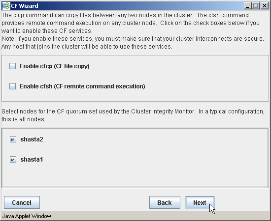
The CIM configuration window in Figure 1.18 has the following parts:
The upper portion allows you to enable cfcp and cfsh.
cfcp is a CF-based file copy program. It allows files to be copied among the cluster hosts. cfsh is a remote command execution program that, similar to cfcp, works between nodes in the cluster. The use of these programs is optional. In this example these items are not selected. If you enable these services, however, any node that has access to the cluster interconnects can copy files or execute commands on any node with root privileges.
The lower portion allows you to determine which nodes should be monitored by CIM.
This window also lets you select which nodes should be part of the CF quorum set. The CF quorum set is used by the CIM to tell higher level services when it is safe to access shared resources.
Note
Do not change the default selection of the nodes
A checkbox next to a node means that node will be monitored by CIM. By default, all the nodes are checked. For almost all configurations, you will want to have all the nodes monitored by CIM.
This window will also allow you to configure CF Remote Services. You can enable either remote command execution, remote file copying, or both.
Note
Enabling either of these means that you must trust all the nodes on the CF interconnects and the CF interconnects must be secure. Otherwise any system able to connect to the CF interconnects will have access to these services.
To use RMS, make sure to configure cfcp and cfsh.
Click on the Next button to go to the summary window.
Figure 1.21 Summary window
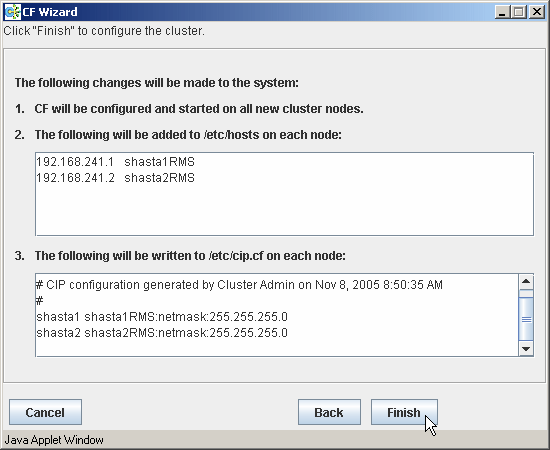
This window summarizes the major changes that the CF, CIP, and CIM Wizards will perform. When you click on the Finish button, the CF Wizard performs the actual configuration on all the nodes.
A window similar to the following figure is displayed while the configuration is being done.
Figure 1.22 Configuration processing window
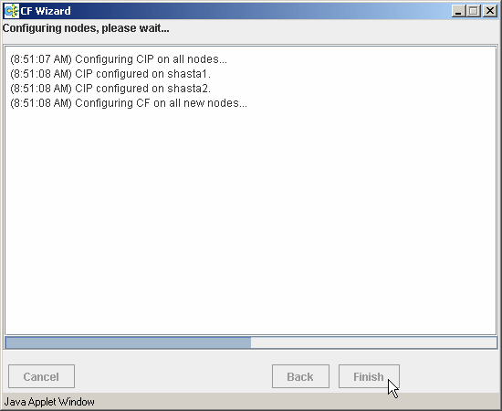
This window is updated after each configuration step. When the configuration successfully completes, a small completion pop-up window appears.
Figure 1.23 Configuration completion pop-up
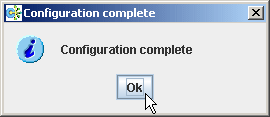
Click on the OK button to close the pop-up window. The configuration processing window now has a Finish button.
Figure 1.24 Configuration window after completion
![]()
When the CF wizard is executed on the unconfigured node, it requests the CF driver to push CF modules to each Ethernet devices on the system. By this process, CF executes ping of each interface. This will enable the CF wizard to detect the network topology.
However, this unloading process may fail. To solve this problem, unload the driver on the error node, and then load the driver again. The unloading process is simplified by using GUI. See "4.6 Starting and stopping CF" for details.
When the window is closed by clicking the Finish button, following pop-up window is displayed.
Figure 1.25 SF wizard start notification pop-up
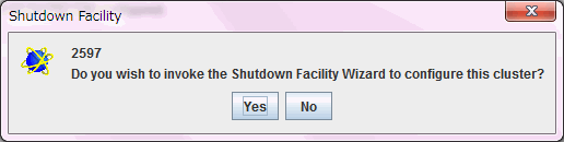
Click on the No button to close the pop-up window.
Point
For a cloud environment or an RHOSP environment, check the following:
Execute the following command on either node to make sure that all the nodes have already joined in the cluster.
# cftool -nExample:
# cftool -n
Node        Number State       Os        Cpu
shasta1       1      UP          Linux     EM64T
shasta2       2      UP          Linux     EM64T
In this example, make sure that both shasta1 and shasta2 are displayed in Node, and the State is in UP status.
Execute the following command on all the nodes to make sure that the CF over IP configuration is enabled.
# cftool -dExample:
# cftool -d
Number  Device    Type Speed    Mtu      State  Configured  Address
4       /dev/ip0  6    n/a      1392     UP     YES         0a.00.00.c9.00.00
In this example, make sure that /dev/ip0 is only displayed in Device.
If the above procedure a or b is not performed correctly, make sure that the configurations of the security groups (or security rules) created with the following references are properly set.
For an FJcloud-O environment, see "3.1.2.4 Creating the Security Group for the Cluster Interconnect" in "PRIMECLUSTER Installation and Administration Guide Cloud Services."
For a NIFCLOUD environment, see "8.3.2.2 Rules Applied to the Cluster Interconnect" in "PRIMECLUSTER Installation and Administration Guide Cloud Services."
For an AWS environment, see "20.3.2.2 Rules Applied to the Cluster Interconnect" in "PRIMECLUSTER Installation and Administration Guide Cloud Services."
For an Azure environment, see "26.3.2.2 Security Rules Applied to the Cluster Interconnect" in "PRIMECLUSTER Installation and Administration Guide Cloud Services."
For an RHOSP environment, see "I.2.2.2 Creating Virtual Network" in "PRIMECLUSTER Installation and Administration Guide."
Also, when creating multiple virtual network interfaces and using a virtual network interface, for which a default gateway is not set, to communicate with interfaces on different subnets, see "21.1.3 Setting Instances" in "PRIMECLUSTER Installation and Administration Guide Cloud Services" and make sure that the configuration of the routing is set so that communication between interconnects can be performed.
If the configurations of the security groups (or security rules) and the configuration of the routing are properly set, execute the following procedure:
Stop CF. For procedures on stopping CF, see "4.6 Starting and stopping CF."
Unconfigure the CF configuration on all the nodes. For procedures on how to unconfigure CF, see "4.12 Unconfigure CF."
Re-execute "5.1.1 Setting Up CF and CIP" in "PRIMECLUSTER Installation and Administration Guide."
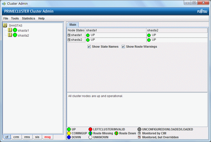
When the CF Wizard is completed, the main window of Cluster Admin will be displayed as below. After a few seconds, the latest information of the CF's configuration and status will be updated and displayed on it.
Figure 1.26 Main CF window