After RMS starts, the initial state of all objects is Unknown. RMS changes this state after the object has the necessary information for identifying the actual state.
The following is necessary information for identifying the state:
For objects with a detector - First report of the detector
For objects with children - Messages of the children concerning their state
Two conclusions can be drawn from the above:
Leaf objects without a detector are illegal in an RMS configuration, because they cannot generate a detector report and they are not able to logically derive their state from the state of their children. Their state always remains Unknown.
All transitions from the Unknown state are always bottom-up, such as from the leaf object to the userApplication. Every object above the leaf object first requires the state of its children before it is able to determine its own state.
Point
SysNode objects and userApplication objects have no detectors for their physical counterparts. SysNode objects receive a detector report directly from the base monitor. userApplication objects determine their status from their children.
After the userApplication object exits the Unknown state, the initializing process of the application ends. From this point, RMS controls the application.
The initializing processes of userApplication objects are independent of each other. Therefore, one userApplication object may be initialized to an Online, Offline, or Standby state while a second userApplication object is still in the Unknown state.
The initializing process of SysNode objects is also independent. A SysNode object exits its initial Unknown state after receiving its detector report.
The Unknown state is a pure initial state. Once an object exits the Unknown state, it does not return to that state.
Example configuration
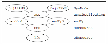
The examples of RMS processing in the following sections are based on an application app configured to run on fuji2RMS and fuji3RMS as follows:
For each node, fuji2RMS and fuji3RMS, there is one SysNode object bearing the name of the node.
For each SysNode where a particular user application may run, the corresponding userApplication object has one child of type andOp, which bears the name of this SysNode as the HostName attribute. The order in which the nodes were defined in the userApplication object determines the priority of the nodes for this application.
The base monitor identifies each andOp object at this level as a local object if the value of the HostName attribute corresponds to the local node's name, and as a remote object if not. The base monitor ignores all remote objects, so that only the local objects and its children are processed.
As children of this logical AND object, the other resources (a Cmdline subapplication and a local file system) are configured according to their internal dependencies.
A diagram of the object hierarchy is shown in the following figure.
Figure 2.1 Object hierarchy for initializing examples

Note that the hierarchy in the figure includes the SysNode objects as parents of the application. While this is often done by convention, these SysNode objects are not dependent on the application objects in any way; however, their presence serves as a reminder of which nodes are represented by the application's child andOp objects. They also appear in the graph generated by the GUI, but in this case their major purpose is to indicate the node where the application is currently running.
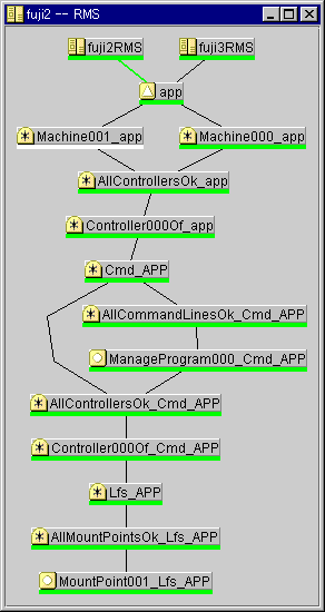
The actual RMS graph for this configuration as produced by RMS Wizard Tools is shown in the following figure.
Figure 2.2 System graph for initializing examples - RMS Wizard Tools

The title bar contains the name of the node on which the graph was drawn, which is fuji2RMS. The line connecting fuji2RMS to app is green, indicating the node where the application is online.
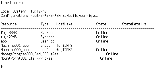
The corresponding output from 'hvdisp -a' is shown in the following figure.
Figure 2.3 hvdisp output for initializing examples - RMS Wizard Tools

To match the hvdisp output, the actual graph includes resource names, which can be displayed by selecting Preferences -> Show Resource Names in Graph in the Cluster Admin rms tab view.
Note that some of the actual object names generated by the RMS Wizard Tools are more complex than the simplified, generic names shown in the abstract graph of Figure 2.1 Object hierarchy for initializing examples. Also, Figure 2.1 Object hierarchy for initializing examples contains additional dependencies that are automatically inserted to ensure proper operation. Selecting other items from the Cluster Admin Preferences menu will display further detail and reveal additional objects and dependencies.
Neither the additional objects nor the complex names in the actual graph are required for a basic understanding of RMS operation. Therefore, to simplify the discussion, the examples in this chapter will focus on the abstract graph and use the generic names.
Example 1
The following process for the configuration illustrated in Figure 2.1 Object hierarchy for initializing examples is applicable for a monitor running on fuji2RMS:
RMS starts.
The base monitor determines the state of the SysNode objects.
The detectors of the cmd and lfs resources report their respective states as Offline.
Since it is a leaf object, lfs changes immediately to Offline and reports this state change to its parent.
After receiving the detector report and the report of its child, cmd possesses the necessary information for determining its own state. It then goes offline and notifies this change of state to its parent andOp1.
Point
andOp2 is a remote object which is ignored by the base monitor on fuji2RMS.
andOp1 is a logical object which has no detector. It uses the message of the child to determine its own state as Offline and notifies this change of state to app.
app is also an object without a detector. When the child andOp that corresponds to the local node goes offline, app also goes offline.
All local child objects of app have exited the Unknown state and the initializing procedure is complete.