The following will define the network configuration required by the system.
For each server, choose the network interfaces to use for the following purposes.
Network interface assigned to the admin LAN
Network interface assigned to the iSCSI LAN (Only when iSCSI is used)
Network interface assigned to the public LAN
Choose the following settings to fit the system environment.
Network redundancy settings
Network Configuration of LAN Switch Blades (when using PRIMERGY BX Servers)
Refer to "Example of VLAN network configuration (with PRIMERGY BX600)" and the description below to design a network configuration.
Admin LAN
The admin LAN is the network used by the manager to communicate with agents on the managed servers and other managed devices.
Admin Server and Managed Servers
The number of network interfaces required for the admin server and managed servers can be determined as follows.
For a non-redundant configuration: one network interface
For a redundant configuration: two network interfaces
If HBA address rename is used, two network interfaces (named NIC1 and NIC2) are required regardless of network redundancy.
For details, refer to "Required Network Configuration when Using HBA address rename".
For PRIMERGY Managed Servers
For a non-redundant configuration
NIC1 (Index1)
For a redundant configuration, or when using HBA address rename
NIC1 (Index1) and NIC2 (Index2)
The NICs above used by managed servers are the default values, and they can be changed when registering managed servers.
For details, refer to "7.3.2 Registering Blade Servers" or "7.4.1 Registering Rack Mount or Tower Servers" in the "User's Guide VE".
For PRIMEQUEST Managed Servers
For a non-redundant configuration
The smallest NIC number of the GSPB allocated to a partition (*)
For a redundant configuration
The smallest and second smallest Onboard LAN NIC numbers of the GSPB allocated to a partition (*)
* Note: For the PRIMEQUEST 2000 series, take "GSPB" as meaning "IOU". For Extended Partition, allocate IOU GbE.
Information
For blade servers, depending on the model of LAN switch blade used in the same chassis, the network interfaces whose index numbers are between 3 and 6 (NIC3 - NIC6) may not be available.
Admin client
Set up routing to enable communications from the admin client to the admin server. It is also suggested to allow communications from the admin client to managed servers, server management units, and switch blades. Such routing configuration is necessary to allow access to ServerView and other management consoles.
There is no need to set up routing if the admin client is already located within the admin LAN.
Note
When using blade servers, connecting the management blade to a LAN switch blade will make the management blade inaccessible in the event of a LAN switch blade failure. Therefore, it is recommended that the management blade be connected to the admin LAN using a LAN switch outside the chassis.
When performing I/O virtualization using HBA address rename, if specifying a 10Gbps expansion card (NIC) for the admin LAN, backup and restore, and cloning cannot be used.
Do not place a DHCP server or a PXE server on the admin LAN.
Do not configure multiple IP addresses for network interfaces used on the admin LAN.
When the same cloning image is deployed to multiple servers, IGMP snooping should be enabled on admin LAN switches. If IGMP snooping is not enabled, transfer performance may deteriorate when ports with different speeds co-exist in the same network, or multiple image operations are run simultaneously.
For PRIMERGY BX900/BX400 LAN switch blades operating in IBP mode, the admin LAN should not be included in the ServiceLAN or the ServiceVLAN group configuration.
Do not change the MTU value for the admin LAN from the default (1500).
iSCSI LAN
The iSCSI LAN is designed for communication between managed servers and storage devices.
The number of network interfaces required for managed servers is as follows:
For a non-redundant configuration: one network interface
For a redundant configuration: two network interfaces
The iSCSI LAN must be a different LAN from the public and admin LANs.
Note
Keep the following points regarding the iSCSI LAN in mind.
Tagged VLANs cannot be used.
Teaming is not available.
Use is not possible in cluster configurations.
The STP of connected switches must be turned off.
DHCP cannot be used for iSCSI LAN IP addresses. Fixed IP addresses should be configured.
Refer to the hardware manual for details on other points.
Public LAN
The public LAN is the network used by managed servers to provide services over internal or external networks (such as intranets or the Internet).
It is recommended to use a NIC other than the one for the admin LAN when using a public LAN for managed servers, in order to prevent admin LAN communication being affected.
Regarding advisory notes for network settings used by VM guests, refer to "Configuration Requirements for Each Server Virtualization Product" of "9.2.1 Configuration Requirements".
A network interface can be shared between multiple public LANs by using a redundant configuration and tagged VLAN.
Information
For blade servers, depending on the model of LAN switch blade used in the same chassis, the network interfaces whose index numbers are between 3 and 6 (NIC3 - NIC6) cannot be used.
Instead, it is possible to use two more interfaces for the public LAN by adding expansion cards (NIC7 and NIC8) and a LAN switch blade, or by sharing the NIC used for the admin LAN.
All network interfaces shared between the admin LAN and the public LAN for managed servers should be configured with tagged VLAN IDs.
Network Configuration of LAN Switch Blades (when using PRIMERGY BX Servers)
In a blade system environment, multiple subnets can be consolidated onto LAN switch blades by using VLANs.
For PRIMERGY BX900/BX400 LAN switch blades operating in IBP mode, the above can also be achieved by using port group settings for IBP instead of VLAN settings.
Each port of a LAN switch blade can be set with VLAN IDs.
Only those ports set with a same VLAN ID can communicate with each other.
Setting up different VLAN IDs then results in multiple subnets (one per VLAN ID) co-existing within the same switch.
Define the VLANs to set on both the internal (server blade side) and external ports of each LAN switch blade.
Internal Ports
Ensure that port VLANs are configured for the ports corresponding to the NICs (refer to "Admin LAN") connected to the admin LAN.
If NICs connected to the admin LAN are used for public LANs, configure tagged VLANs.
For the ports corresponding to the NICs (refer to "Public LAN") connected to the public LAN, assign a VLAN ID (port or tagged VLAN) other than VLAN ID1 (the default VLAN ID) for each subnet.
Using tagged VLANs on LAN switch ports also requires configuring the network interfaces of managed servers with tagged VLANs. As Resource Orchestrator cannot set tagged VLANs to network interfaces on managed servers, this must be done manually.
External Ports
Choose the LAN switch blade ports to connect to external LAN switches, and the VLAN IDs to use for both the admin and public LANs.
When choosing a tagged VLAN configuration, the VLAN ID chosen for a LAN switch blade's external port must be the same as that used on its adjacent port on an external LAN switch.
Note
To change the VLAN ID for the admin LAN, perform the following.
Enable communications between the admin server and the LAN switch blade.
Manually change the following two settings.
- Change the VLAN ID of the external port(s) used for the admin LAN.
- Change the VLAN ID used by the admin IP address of the LAN switch blade.
Change the VLAN ID used by the managed server on the admin LAN.
VLAN settings for LAN switch blades are not included in cloning images. Configure VLAN settings for the target servers before deploying a cloning image.
In the following cases, VLANs cannot be configured using the ROR console.
Configuring VLANs on external ports
Link state group
Port backup function
LAN switch blade PY CB DCB SW 10Gb 18/6/6
Configuring VLANs on internal ports
A LAN switch blade PY CB DCB SW 10Gb 18/6/6 is used, and AMPP has been configured for the internal ports
Configuring VLANs on external and internal ports
Link aggregation
However, the following models are excluded.
- LAN switch blade PY CB Eth Switch/IBP 10Gb 18/8
- LAN switch blade PY CB Eth Switch 10/40Gb 18/8+2 (switch mode, end host mode)
- LAN switch blade PY CB Eth Switch/IBP 1Gb 36/8+2
- LAN switch blade PY CB Eth Switch/IBP 1Gb 36/12
- LAN switch blade PY CB Eth Switch/IBP 1Gb 18/6
Deactivated (depends on LAN switch blade model)
When a LAN switch blade operates in Converged Fabric mode, or when a LAN switch blade PY CB 10Gb FEX Nexus B22 is used
LAN switch blade PY CB DCB SW 10Gb 18/6/6
Each port VLAN configuration must meet all of the conditions below.
Do not configure more than one port VLAN.
Do not configure the same VLAN ID for the port VLAN and the tagged VLAN.
Mount the following LAN switch blades in the connection blade slots except for CB5/6 when using a PRIMERGY BX900 chassis.
LAN switch blade PY CB Eth Switch/IBP 1Gb 36/8+2
LAN switch blade PY CB Eth Switch/IBP 1Gb 36/12
LAN switch blade PY CB Eth Switch/IBP 1Gb 18/6
When using a LAN switch blade PY CB 10Gb FEX Nexus B22 in a PRIMERGY BX900 chassis, server blades installed in slot 17 or slot 18 cannot use internal ports because the switch has only 16 internal ports.
Choose VLAN IDs as well as VLAN types (port or tagged VLAN) for the ports on LAN switch blades that are connected to each server blade's network interfaces. For each of a physical server's network interfaces, choose:
Physical server name
NIC index
VLAN ID
VLAN type (port or tagged VLAN)
Note
On servers, operating systems associate each physical network interface with a connection name (Local area connection X in windows and ethX in Linux).
If more than one network interface is installed, depending on the OS type and the order of LAN driver installation, the index numbers (X) displayed in their connection name may differ from their physically-bound index (defined by each interface's physical mount order).
The relations between physically-bound indexes and displayed connection names can be confirmed using OS-provided commands or tools.
For details, refer to network interface manuals.
Also, note that Resource Orchestrator uses the physical index of a network interface (based on physical mount order).
[Windows] [Hyper-V]
When using the backup, restore, or cloning functions, enable the managed server's NetBIOS over TCP/IP.
Note that the managed server should be restarted after enabling NetBIOS over TCP/IP.
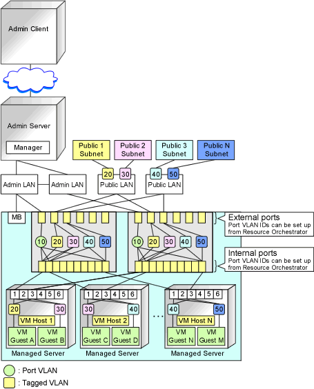
Example of VLAN Network Configuration (with PRIMERGY BX600)
Figure 7.1 With Port VLANs
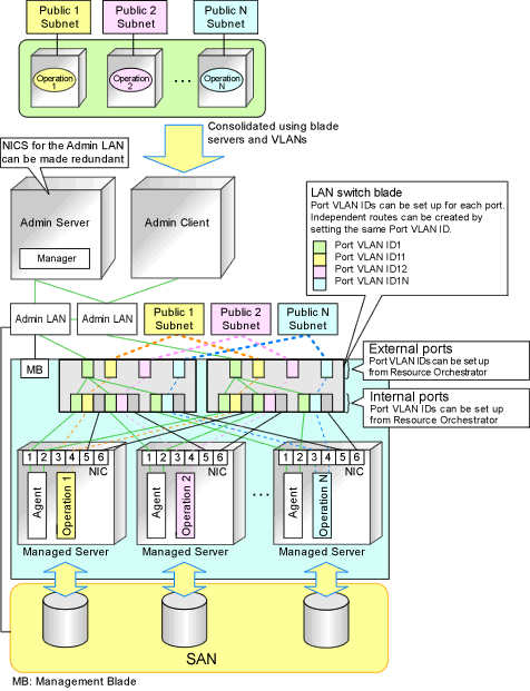
Figure 7.2 With Tagged VLANs
Information
It is recommended that a dedicated admin LAN be installed as shown in "Example of VLAN network configuration (with PRIMERGY BX600)".
If you need to use the following functions, a dedicated admin LAN is required in order to allocate admin IP addresses to the managed servers using the DHCP server included with Resource Orchestrator.
Backup and restore
Collection and deployment of cloning images
HBA address rename
In a configuration using a LAN switch blade, a VLAN has to be configured if the LAN switch blade is shared by an admin and public LANs where a dedicated admin LAN is required.
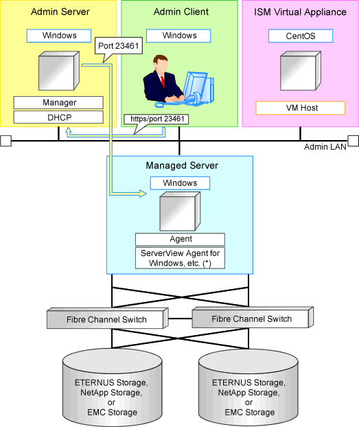
Network Configuration Required for ISM Coordination
In order to coordinate with ISM, install the ServerView Infrastructure Manager virtual appliance on a server other than the admin server.
For details, refer to the manuals of ServerView Infrastructure Manager.
For details on how to configure ISM coordination settings, refer to "7.1 Registering VIOM/ISM Coordination" in the "User's Guide VE".
The following diagram shows an example of how the HBA address rename setup service can be configured.
Figure 7.3 Sample Configuration for ISM Coordination (With an External DHCP Server)
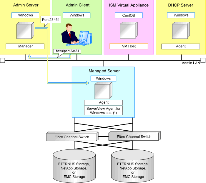
Figure 7.4 Sample Configuration for ISM Coordination (Without an External DHCP Server)
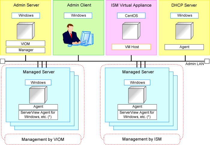
Example of System Configuration Using I/O Virtualization (In an Environment in which ISM and VIOM Co-Exist)
An example system configuration in an environment in which ISM and VIOM co-exist is given below.
The PRIMERGY BX managed servers are registered for management by VIOM.
The PRIMERGY RX managed servers are registered for management by ISM.
Figure 7.5 Sample System Configuration in an Environment in which ISM and VIOM Co-Exist
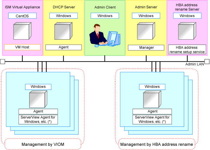
Example of System Configuration Using I/O Virtualization (In an Environment in which ISM and HBA address rename Co-Exist)
An example system configuration in an environment in which ISM and HBA address rename co-exist is given below.
None of the managed servers are managed by both ISM and HBA address rename.
Figure 7.6 Sample System Configuration in an Environment in which ISM and HBA address rename Co-Exist
Required Network Configuration when Using HBA address rename
At startup a managed server set with HBA address rename needs to communicate with the Resource Orchestrator manager. To enable startup of managed servers even when the manager is stopped, Resource Orchestrator should be set according to one of the following configurations.
Manager cluster configuration with admin LAN redundancy using the redundant line control function of GLS
For details, refer to "Appendix C Manager Cluster Operation Settings and Deletion" in the "Setup Guide VE".
A dedicated HBA address rename server
This section describes the network configuration that is required for an environment with a dedicated HBA address rename server.
For details of settings for the HBA address rename setup service, refer to "6.1 HBA address rename Setup Service" in the "Setup Guide VE".
This service must be placed in an admin LAN in the same segment as the admin server.
Only one HBA address rename setup service operates on the admin LAN. Do not start more than one instance of this service.
This service uses NIC2 (Index2).
Connect NIC2 of the managed server to the admin LAN.
NIC2 is the default value, and it can be changed when registering managed servers.
For details, refer to "7.3.2 Registering Blade Servers" or "7.4.1 Registering Rack Mount or Tower Servers" in the "User's Guide VE".
This service periodically obtains information about managed servers from the admin server and operates using this information. For this reason, it should be installed on a server that can be left active all the time.
There must be two LAN cables between LAN switches (cascade connection) on the admin server and on the managed server.
Note
The HBA address rename setup service cannot operate on the same server as ServerView Deployment Manager, or on a server where any other DHCP or PXE service is running.
The following diagram shows an example of how the HBA address rename setup service can be configured.
Figure 7.7 Sample Configuration Showing the HBA address rename Setup Service (with PRIMERGY BX600)
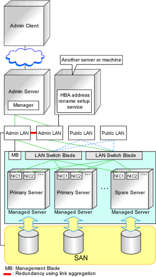
Connections between LAN switches on the admin LAN can be made redundant using link aggregation.
Connect NIC2 (Index2) to the admin LAN (when it is the default).
Configure the HBA address rename setup service on a server connected to the admin LAN. This server must be different from the admin server.
Ensure that the server or personal computer that is used to operate the HBA address rename setup service is always on when the managed servers are active.
Network Configuration Required for VIOM Coordination
When coordinating with VIOM, the network configuration is defined by LAN switch blades and IBPs.
For details, refer to the ServerView Virtual-IO Manager manual.
For details on how to configure VIOM coordination settings, refer to "7.1 Registering VIOM/ISM Coordination" in the "User's Guide VE".
The following diagram shows an example of how the HBA address rename setup service can be configured.
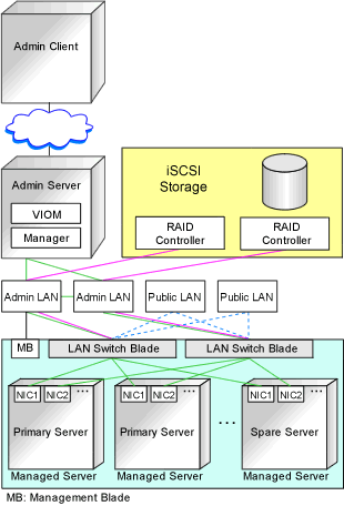
Figure 7.8 Sample Configuration for VIOM Integration (on PRIMERGY BX900 Servers Using a SAN)
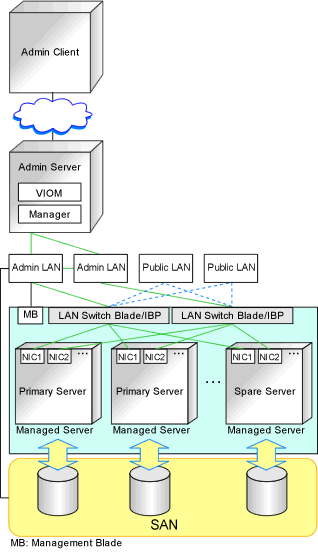
Figure 7.9 Sample Configuration for VIOM Integration (on PRIMERGY BX900 Servers Using iSCSI)
When using IBPs, the first IBP port should be connected to the admin LAN.
On the adjacent admin LAN switch, the Spanning Tree Protocol (STP) should be disabled on the port connected to that first IBP port.
Functions Provided by Resource Orchestrator
Resource Orchestrator provides the following VLAN and port group management functions for PRIMERGY BX LAN switch blades.
VLAN configuration using the GUI
VLAN IDs of LAN switch blade ports can be configured from the ROR console.
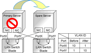
Exchange of VLAN IDs within each LAN switch blade in conjunction with server switchovers
When a server switchover occurs, the VLAN ID configuration of related LAN switch blades is automatically adjusted to preserve the network connectivity of applications.
VLAN IDs that were set on the LAN switch blade ports connected to the original server are exchanged with the VLAN IDs set on the ports connected to the spare server, as shown in "Figure 7.10 VLAN Exchange Mechanism for Auto-Recovery, Server Switchover, and Server Failback".
Figure 7.10 VLAN Exchange Mechanism for Auto-Recovery, Server Switchover, and Server Failback
Exchange of port groups in LAN switch blades during server switchovers
When a server switchover occurs, the port group configuration of related LAN switch blades (if in IBP mode) is automatically adjusted to preserve the network connectivity of applications.
Note
The targets of such VLAN ID and port group exchanges are the LAN switch blade ports connected to the switched over managed servers. If the switched over servers are connected to different LAN switch blades (e.g. when switching over managed servers in different chassis) the external ports of those LAN switches should be set with the same VLAN or port group configuration, and the switch blades placed in the same network.
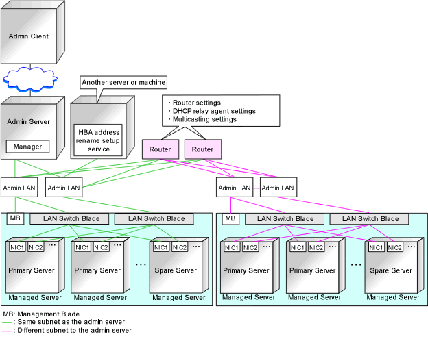
Network Configuration in Cases with Multiple Admin LAN Subnets
In cases with multiple admin LAN subnets, configure the router settings.
For details on how to configure these settings, refer to "7.6 Configuring the Network Environment".
The following diagram shows an example of how configuring the network environment can be performed.
Figure 7.11 Network Configuration Example Involving Multiple Admin LAN Subnets