This section describes how to change the configuration of a virtual switch.
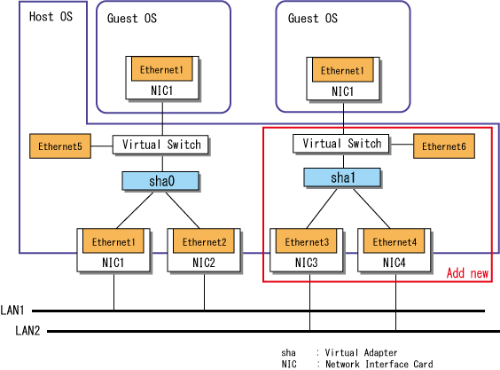
This section describes how to add a virtual switch under the following conditions.
Figure B.3 Adding a Virtual Switch
Stop all ping monitoring.
> hanetpoll off FJSVhanet: INFO: 00000: The command ended normally. |
Create a new virtual adapter.
Specify the GLS virtual adapter sha1 to bundle the physical adapters (Ethernet 3 and Ethernet 4) and execute the create subcommand of the hanetconfig command.
> hanetconfig create -n sha1 -t "Ethernet 3","Ethernet 4" -v hv FJSVhanet: INFO: 00000: The command ended normally. |
Check the settings.
Execute the print subcommand of the hanetconfig command.
> hanetconfig print Name VID Adapters +--------+----+----------------------------------------------------------+ sha0 hv Ethernet 1,Ethernet 2 sha1 hv Ethernet 3,Ethernet 4 |
Activate the GLS virtual adapter sha1 by executing the strhanet command.
> strhanet -n sha1 FJSVhanet: INFO: 00000: The command ended normally. |
Connect the GLS virtual adapter sha1 to the Hyper-V virtual switch.
For details, see "B.3.1.4 Creating a Virtual Switch."
Create a network adapter on a guest OS by using the virtual switch created in step 5.
For details, see "B.3.1.5 Creating a Network Adapter on a Guest OS."
Set the scripts for Hyper-V.
For details, see "B.3.1.6 Setting Scripts for Hyper-V."
See
To ensure that GLS is set and functions correctly, perform the ping monitoring setting after adding virtual switches.
For details, see "5.3.2 Setting Ping Monitoring."
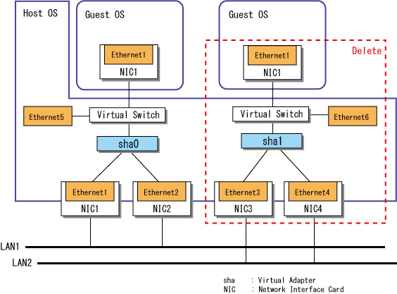
This section describes how to delete a virtual switch under the following conditions.
Figure B.4 Deleting a Virtual Switch
Stop guest OSes connected to the Hyper-V virtual switch. with which the GLS virtual adapter sha1 to be deleted is registered.
Open the setting window for guest OSes from [Hyper-V Manager] and set the configuration to [Not connected] for the network adapter connected to the virtual switch which is the target to be deleted. Delete the network adapter if you do not use it after deleting the virtual switch.
Stop ping monitoring on the GLS virtual adapter sha1 to be deleted.
> hanetpoll off -n sha1 FJSVhanet: INFO: 00000: The command ended normally. |
Change the settings of the virtual switch with which the GLS virtual adapter sha1 to be deleted is registered.
From the [Hyper-V Manager] window, select [Virtual Switch Manager].
Select the virtual switch you need to delete and click the [Remove] button.
Delete the scripts for Hyper-V.
> del "<GLS Installation Folder>\usr\script\adapter\sha1.bat" |
For details, see "B.3.2.2 Restarting the Transmission for Network Switching."
Deactivate the GLS virtual adapter sha1 to be deleted by executing the stphanet command.
> stphanet -n sha1 FJSVhanet: INFO: 00000: The command ended normally. |
Check whether the ping monitoring is set.
> hanetpoll print |
If ping monitoring is not set, step 8 is not applicable.
If you have set the ping monitoring, delete the corresponding settings.
Execute the delete subcommand of the hanetpoll command for the physical adapters bundled in the GLS virtual adapter sha1, which is to be deleted.
> hanetpoll delete -t "Ethernet 3" FJSVhanet: INFO: 00000: The command ended normally. > hanetpoll delete -t "Ethernet 4" FJSVhanet: INFO: 00000: The command ended normally. |
Delete the information defining the virtual adapter.
Delete the GLS virtual adapter sha1 by executing the delete subcommand of the hanetconfig command.
> hanetconfig delete -n sha1 FJSVhanet: INFO: 00000: The command ended normally. |
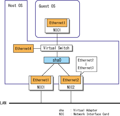
This section describes how to change the physical adapters bundled into a virtual adapter. In the procedure below, the name of the virtual adapter is sha0. This virtual adapter contains two physical adapters: Ethernet 1 and Ethernet 2. In the procedure below, Ethernet 2 is replaced with Ethernet 3.
Figure B.5 Changing Physical Adapters
For details on how to change, see "5.2.3 Changing Physical Adapters."