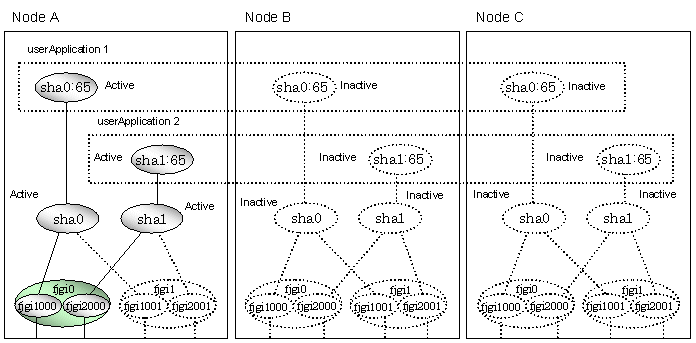
This section explains the transfer route multiplexing using tagged VLAN interface that operates on a cluster system.
When specifying tagged VLAN interfaces for creating a virtual interface, the ones on disparate physical interfaces must be used. The figure below illustrates tagged VLAN interface multiplexing on a cluster system (standby).
Figure 5.34 Tagged VLAN interface multiplexing on Fast switching mode (Standby)
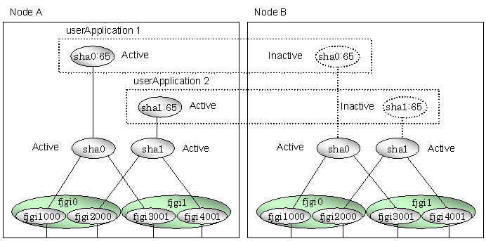
When specifying tagged VLAN interfaces for creating a virtual interface, the ones on disparate physical interfaces must be used. The figure below illustrates tagged VLAN interface multiplexing on a cluster system (standby).
Figure 5.35 Tagged VLAN interface multiplexing on NIC switching mode (Standby)
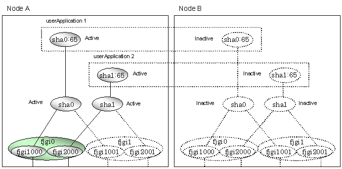
When specifying tagged VLAN interfaces for creating a virtual interface, the ones on disparate physical interfaces must be used. The figure below illustrates tagged VLAN interface multiplexing on a cluster system (Mutual standby).
Figure 5.36 Tagged VLAN interface multiplexing on Fast switching mode (Mutual Standby)
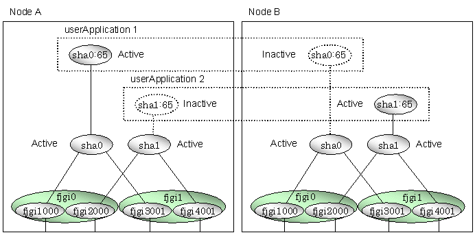
When specifying tagged VLAN interfaces for creating a virtual interface, the ones on disparate physical interfaces must be used. The figure below illustrates tagged VLAN interface multiplexing on a cluster system (Mutual standby).
Figure 5.37 Tagged VLAN interface multiplexing on NIC switching mode (Mutual Standby)
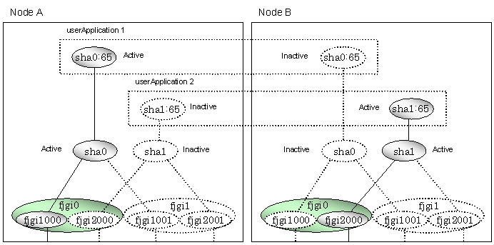
When specifying tagged VLAN interfaces for creating a virtual interface, the ones on disparate physical interfaces must be used. The figure below illustrates tagged VLAN interface multiplexing on a cluster system (Cascade).
Figure 5.38 Tagged VLAN interface multiplexing on Fast switching mode (Cascade)
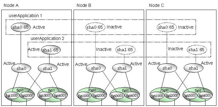
When specifying tagged VLAN interfaces for creating a virtual interface, the ones on disparate physical interfaces must be used. The figure below illustrates tagged VLAN interface multiplexing on a cluster system (Cascade).
Figure 5.39 Tagged VLAN interface multiplexing on NIC switching mode (Cascade)
