This section describes on transfer route multiplexing using tagged VLAN interfaces.
Note
Transfer route multiplexing with tagged VLAN is not available in RIP and GS/SURE modes.
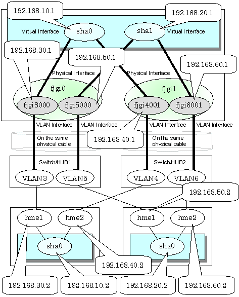
When bundling a tagged VLAN interface on Fast switching mode, specify the tagged VLAN interface instead of the physical interface. Figure 3.12 Fast switching mode with tagged VLAN interface illustrates bundled tagged VLAN architecture.
Note
You cannot create a virtual interface by bundling two tagged VLAN interfaces emerged from a single physical interface. Please be sure to specify the tagged VLAN interfaces on disparate physical interfaces when creating a virtual interface for Fast switching mode.
You cannot mix tagged and untagged VLANs. VLANs can only contain tagged or untagged ports.
See
Refer to "7.1 hanetconfig Command" for configuring an interface bundled with Fast switching mode.
Figure 3.12 Fast switching mode with tagged VLAN interface illustrates an example of using tagged VLAN interface on Fast switching mode.
Figure 3.12 Fast switching mode with tagged VLAN interface

When using a tagged VLAN interface on NIC switching mode, specify the tagged VLAN interface instead of a physical interface at configuration.
In addition, when tagged VLAN interfaces on the same physical network cable is made redundant by two or more virtual interfaces, the mode to "synchronized switching" or "asynchronous switching" operation is defined. Below, operation of "synchronized switching" and "asynchronous switching" is explained.
See
For configuration of monitoring target, refer to "7.7 hanetpoll Command".
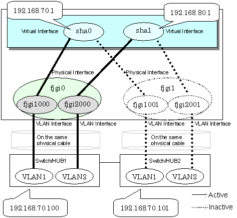
Synchronized switching of virtual interfaces
In Two or more virtual interfaces which bundle multiple tagged VLAN interfaces redundantly, by defining the same monitoring target IP address, all virtual interfaces are synchronous switching, when failure occurs in monitoring of transfer path. When the IP address for management can define only one as switch/HUB of a monitoring target, "synchronous switching" of a virtual interface is chosen.
Figure 3.13 NIC switching mode with tagged VLAN interface (synchronized switching) illustrates of synchronous switching architecture.
Figure 3.13 NIC switching mode with tagged VLAN interface (synchronized switching)

Asynchronous switching of virtual interfaces
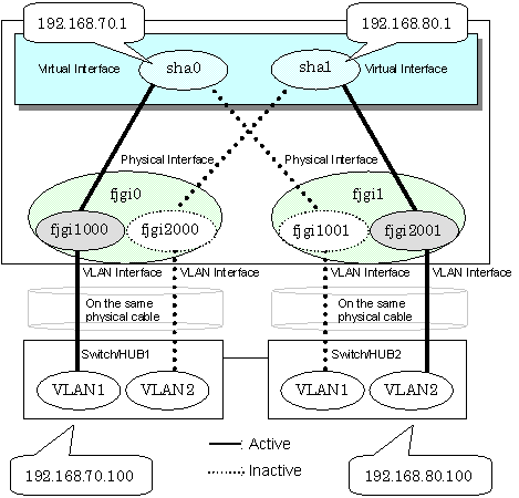
Contrary to a synchronous switching, two or more virtual interfaces which bundle multiple tagged VLAN interfaces, can be switched asynchronously. In this case, the monitoring target IP address from which it differs for every virtual interface is defined as monitoring target information.
When two or more definitions of the IP address for management are possible to switch/HUB used as a monitoring target, the asynchronous switching of the virtual interfaces is chosen to use Standby NIC effectively.
Point
When the IP address for management can set only one as switch/HUB used as a monitoring target, in order to perform the asynchronous switching of the virtual interfaces, please define the IP address for management of switch/HUB as one certain virtual interface, and define other connection equipment or remote hosts as a monitoring target about other virtual interfaces.
Figure 3.14 NIC switching mode with tagged VLAN interface (asynchronous switching) illustrates of asynchronous switching architecture.
Figure 3.14 NIC switching mode with tagged VLAN interface (asynchronous switching)

Note
On NIC switching mode, if several tagged VLAN interfaces exist on two physical interfaces, and at lease two virtual interfaces are created on pairs of those tagged VLAN interfaces, please ensure that you configure the standby patrol function exclusively on a single virtual interface. For example, say virtual interface (sha0) is created on two tagged VLAN interfaces "fjgi1000" and "fjgi1001", and similarly, another virtual interface (sha1) is created on "fjgi2001" and "fjgi2000", the standby patrol function must be configured on either one of the virtual interfaces (sha0 or sha1).
On NIC switching mode, tagged VLAN interfaces on a pair of physical interfaces should be used to create multiple virtual interfaces, if tagged VLAN networks are used. For example, you cannot have an environment where a virtual interface is created on a pair of VLAN interfaces "fjgi1000" and "fjgi1001", and another virtual interface is created on a pair of VLAN interfaces "fjgi2001" and "fjgi2002" because the physical interface "fjgi1" is the only shared physical interface here.
When using synchronized switching mode with tagged VLAN interfaces, only one virtual interface is selected to switch/HUB monitoring. Its interface address is the nearest to monitoring target.
If you specify two monitoring targets with synchronized switching mode, please specify two network addresses which belong to the same network. If their network addresses are different, switch/HUB monitoring cannot operate normally, because they are assigned to only one virtual interface.
When configuring a standby patrol function for a virtual interface which is using the tagged VLAN interfaces, it is required to reboot the OS in order to enable the standby patrol function. GLS withholds a modification of MAC address of the secondary interface, so that it prevents communication errors on other tagged VLAN interfaces which are sharing a physical communication line.
When the physical IP address takeover function of the NIC switching mode is used, a virtual interface cannot be synchronized switched.