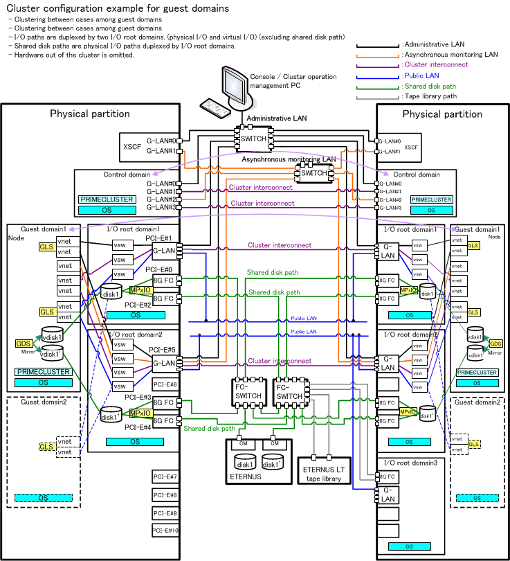
This section presents a sample layout for a PRIMECLUSTER system in an Oracle VM Server for SPARC Environment. Use it for reference when designing your system.
System Configuration
Figure 12.1 Sample System Configuration

Utilized Hardware
SPARC M10-4
Utilized Software
Solaris 11
Enhanced Support Facility 3.2
PRIMECLUSTER 4.3
Oracle VM Server for SPARC Manager Software 1.0.3
Internet Explorer 9 (installed on administrator PC)
Java(TM) 2 Platform Standard Edition Runtime Environment Version 6 (installed on administrator PC)
Shared Disk Storage System Settings
Device Name | LUs | RAID Groups | RAID Level | Size |
|---|---|---|---|---|
ETERNUS DX8100 S2 (FC) | 4 | 1 | 5 | 248.2 GB |
Note
For using the disk storage system with UNIX, the disks must be formatted beforehand with the "format(1M)" command.
When you plan to format the disk storage system as part of your cluster system setup works, take sufficient time for formatting into consideration.
Sample Settings for Virtual Network
Node | Name of Control Domain | Name of Physical NIC | Name of Virtual Switch | Name of Guest Domain | Name of Virtual NIC |
|---|---|---|---|---|---|
primecl01 | primary | e1000g0 | primary-vsw0 | guest01 | vnet0 |
e1000g1 | primary-vsw1 | guest01 | vnet1 | ||
primecl02 | primary | e1000g0 | primary-vsw0 | guest02 | vnet0 |
e1000g1 | primary-vsw1 | guest02 | vnet1 |
In the control domain, create virtual switches primary-vsw0 and primary-vsw1 using physical NICs e1000g0 and e1000g1, and add vnet0 and vnet1 as virtual NICs to be used in the guest domains. Use GLS to create redundant virtual NICs in each domain. Specify vsw0 and vsw1 in the control domain as well as vnet0 and vnet1 in the guest domains as virtual NICs to be made redundant by GLS.
Note
Settings for the virtual network are made by running the ldm(1M) command in the control domain.
Network adapters used in virtual networks must be compliant with GLDv3.