In cluster system, Redundant Line Control Function supports the following operation modes:
Active standby (1:1 and N:1)
Mutual standby
Cascade
Priority transfer
Duplicate transfer path for SIS
How cluster failover is dealt with in each mode is shown below.
Mode | Active Standby System | Mutual standby System | Cascade System | Priority transfer system | Duplicate transfer path for SIS |
|---|---|---|---|---|---|
Fast switching mode | A | A | A | A | X |
NIC switching mode | A | A | A | A | A |
Virtual NIC mode | A | A | A | A | X |
GS linkage mode | A | A | X | X | X |
[Meaning of the symbols] A: Supported X: Not supported
Virtual IP addresses allocated to virtual interfaces are taken over if a cluster switching event occurs. GLS does not provide any function to support MAC address takeover and system node name takeover.
In addition, physical interfaces used by virtual interfaces cannot be set as takeover targets (MAC address and IP address) for the cluster.
In Virtual NIC mode, IP addresses are not taken over, and only node switching can be performed independently in the event of a line failure.
Table 5.2 Supported cluster take over information indicates the support status of each takeover function.
Cluster Operation mode | IP address | MAC address | IP address | IP address | IP address |
|---|---|---|---|---|---|
Active standby | A | X | X | X | X |
Mutual standby | A | X | X | X | X |
Cascade | A | X | X | X | X |
Priority transfer | A | X | X | X | X |
[Meaning of the symbols] A: Supported X: Not supported
Note
Configuring GLS as Priority transfer, one of the cluster operation, follows the same procedure for configuring Cascade operation.
When using Fast switching mode, you need a host running Fast switching mode as an associate host other than a node configuring a Cluster system. Failover of Gls resource may fail if there is only one Cluster system configuring nodes on the transfer route monitoring host due to simultaneous detection of transfer route failure on operation node and standby node.
When multiple virtual machines are created on one server to set up a cluster configuration, and Fast switching mode is used, an error will not occur to the cluster resources, even if a failure occurs to a switch which exists outside of the server. This is because a configuration is for successful monitoring at any time in the virtual switch in which multiple virtual machines are connected.
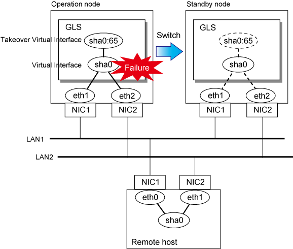
Figure 5.1 Cluster Switching for the virtual interface shows an example of cluster switching for the virtual interface
Figure 5.1 Cluster Switching for the virtual interface

The logical unit number for the virtual interface for cluster switching is 65 or later. (sha0:65, sha0:66)