In this mode, each of multiple NICs (Network Interface Cards) is connected to a different network. Then, all the NICs are activated and used concurrently. Outgoing packets are assigned to the lines in units of TCP connections.
Thus, different lines are used for different connections for communication. If a failure occurs on one of the lines, communication can continue using another line, offering improved line reliability.
As with Fast switching mode, a virtual interface is created and then a virtual network is allocated to it. A TCP/IP application can carry out communication with the remote system, irrespective of the physical network redundant configuration, by using a virtual IP address set in this virtual interface as its own local system IP address.
Figure 2.16 Example of duplicated operation in GS linkage mode
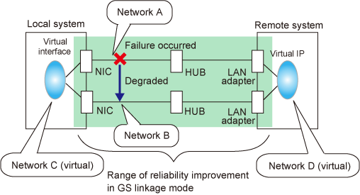
Figure 2.17 Example of duplicated operation in GS linkage mode (Remote network)
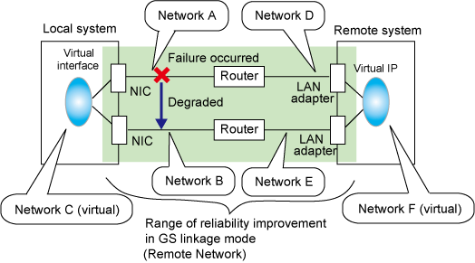
If the GS linkage communication function is to be used, the systems among which communication is to be carried out must be connected on the same network. Connecting systems on different networks is not allowed.
Lines are used in units of TCP connections for communication. If a failure occurs on a line, processing can continue on another line that is normal. Since all the redundant lines are activated for use, each of the lines can be directly used for a different purpose, enabling efficient use of resources.
GS linkage mode is appropriate, for example, for communication in a multi-server environment where GS, PRIMEQUEST, or PRIMERGY are mixed or for IP-based reconstruction of network infrastructures of a legacy system.
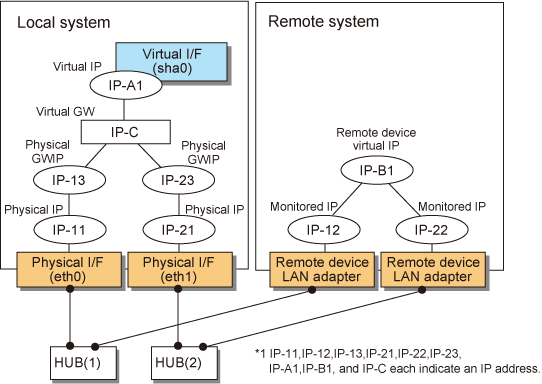
Figure 2.18 System configuration in GS linkage mode and Figure 2.19 System configuration in GS linkage mode show a system configuration of GS linkage mode.
Figure 2.18 System configuration in GS linkage mode
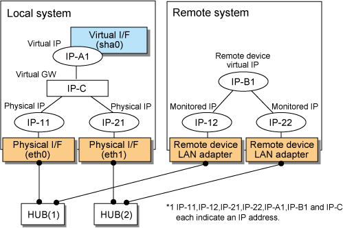
Figure 2.19 System configuration in GS linkage mode
The following explains each component and its meaning:
Indicates a physical interface (such as eth0 and eth1) of the duplicated NIC.
Indicates an IP address to be attached to a physical interface. This IP address is always active. Use the IP address to manage a node by using the cluster operation management view, etc. IPv4 address can be used for a physical interface. IPv6 addresses cannot be used.
Note that the IP addresses to be attached to each physical interface must be different network addresses.
Indicates a virtual interface (such as sha0) used to handle duplicated NICs as one NIC.
Indicates a local IP address to be attached to a virtual interface for communication with remote devices. This IP address is activated on the active node. In cluster operation, the IP address is taken over by the standby node when clusters are switched. IPv4 address can be used for a physical interface. IPv6 addresses cannot be used.
Indicates a virtual gateway to be used for GS linkage mode. Only use the IPv4 address formats. IPv6 addresses cannot be used.
Indicates a cluster environment that connects to GS via a router, representing the physical IP address that will be the gateway for the GLS takeover virtual IP address. In a cluster configuration, this IP address is taken over along with the virtual IP address (takeover virtual IP address) between nodes, which means that you can statically specify the route for the GLS virtual IP address on the router even if the virtual IP address is taken over. In a cluster configuration, set the static route on the router so that the physical GWIP can act as the gateway for the GLS virtual IP address. In a single configuration, set the physical IP address as a gateway, rather than the physical GWIP, so you do not need to set the physical GWIP in a single configuration. The specifiable address format is IPv4. IPv6 addresses cannot be specified.
Indicates a NIC of the relay and remote devices.
Indicates an IP set to the NIC of the remote device. This IP address is monitored. IPv4 address can be used for a physical interface. IPv6 addresses cannot be used.
Indicates a virtual IP of the remote device with which communication should be carried out. IPv4 address can be used for a physical interface. IPv6 addresses cannot be used.
The ping command is issued periodically to the LAN adapter of the remote system and its response is monitored. If no response is received within a specified period of time, the line is considered to be faulty. Also, if a fault notification (with a special packet) of a line is received from the remote system, the line is considered to be faulty (For details, see "2.6.1 Communication target monitoring").
Figure 2.20 Monitoring method in GS linkage mode
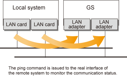
The switching time of a line is indicated by [monitoring interval (sec) X monitoring count (count)]. The monitoring interval can be set in the range of 1 to 300 seconds and the monitoring count can be set in the range of 1 to 300 times. By default, they are 5 seconds and 5 times, respectively.
The following failures can be detected:
Figure 2.21 Detectable failures in GS linkage mode
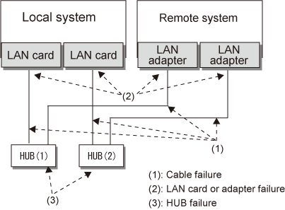
Because the failures (1) - (3) appear to be the same failure, a type of the failure cannot be specified. Each device has to be checked to make this determination.
Monitoring is started automatically when the virtual interface is activated. Monitoring is automatically stopped when the virtual interface is inactivated. For cluster configuration, monitoring is started automatically when a GLS resource status changes to Online or Standby. Monitoring is stopped when all GLS resources change to Offline.
A line whose failure is detected is automatically avoided, and only lines operating normally are used to continue communication.
If a faulty path of a physical interface is recovered, the line of the physical interface is automatically restored for normal communication. The failback of a line cannot be performed manually.
An associated host is able to communicate with the following systems:
Global Server (GS)
PRIMEQUEST
PRIMERGY
The requirement for user applications that can be operated in this mode is as follows:
The virtual IP address of Redundant Line Control function is set so that it is fixed as a local IP address using the bind function or others.
When using a physical interface, it is necessary to assign the IPv4 address.
When using GS linkage mode (GS communication capability), the system must be configured as multi-homed host instead of a router.
Fast switching and NIC switching modes are allowed to coexist in a single node.
This mode cannot be applied for communication between Linux server and Solaris server.
The remote system's GS must support the lookup of the location of virtual IP addresses.
When you connect between GLS and GS via router, set the server with GS linkage mode to send the path for GS's virtual IP using RIPv1.