A Make Choice Trigger makes a choice on an activity in response to data that comes in from an external system.
To define a Make Choice Trigger:
Add the User Defined Attributes (UDAs) you will need for your trigger to the process definition.
Select the Activity Node to display the Properties view for it.
Select the Triggers tab.
Click Add.
A new trigger with a default name is added.
Select the trigger to view the details for that trigger in the Trigger Details area.
Modify the name of your trigger as required on the General sub-tab, in the Trigger Details area.
Optional: Describe the purpose of your trigger on the General sub-tab.
Select the Event sub-tab.
If you have an XML schema that describes the format of the incoming data, type its URL in the URL to XML Schema field. Click Retrieve to load the XML schema.
The icon next to the URL to XML Schema field tells you if the XML schema has been loaded.
If you want the trigger to fire only with certain incoming data, specify a JavaScript expression in the Event Filter field that defines those conditions.
For an example, refer to section 11.9.2 Defining Start Process Triggers. For information on JavaScript expressions, refer to section 11.14 Defining JavaScript Expressions.
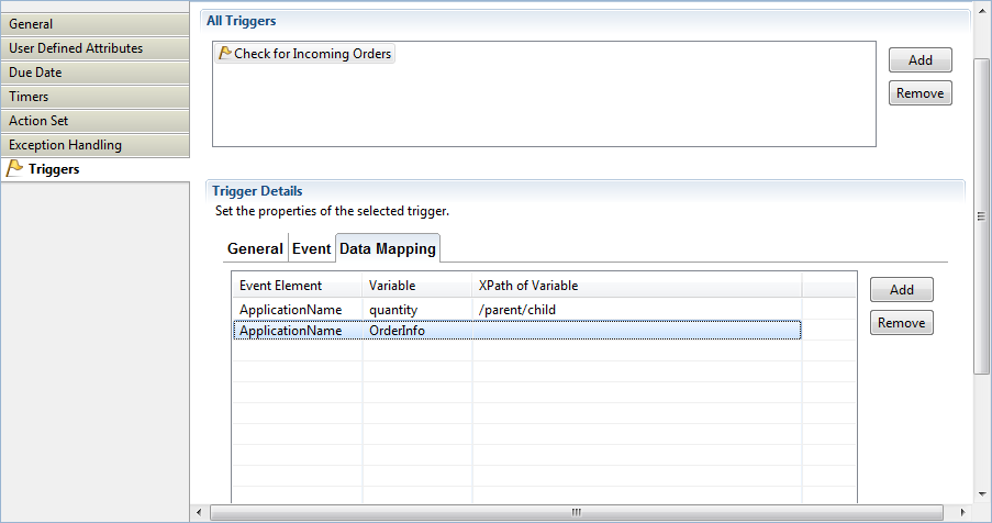
Select the Data Mapping sub-tab. Map the elements of the incoming XML file to UDAs. To map an element:
Click Add.
If you specified an XML schema, select an XML element from the Event Element list.
Select the UDA from the Variable list to which you want to map the XML element.
Note
Triggers are flexible enough so that you can map external data of type String to a UDA of type INTEGER as long as the external data consists only of numerals.
Click in the field in the XPath of Variable column.
Figure 11.41 Defining Data Mappings
Optional: If you want to edit the XPath expression that you selected in the XPath of Variable drop-down list, click the ellipsis (...) button that is displayed next to the XPath of Variable drop-down list. XPath Editor dialog is displayed with the selected XPath expression in its editor area. You can edit this XPath expression and click OK to use the edited XPath expression.
Note
The edited XPath expression is displayed as the latest XPath in the XPath drop-down list.
Note
The XPath expressions related to the selected XML UDA are displayed in the XPath drop-down list. When XML Schema is defined in selected UDA, the XPath list that can be used with this XML Schema is displayed. When Initial value is defined in selected UDA, the XPath list that can be used with this Initial value is displayed. When both are defined, Xpath list of XML Schema is displayed.
Note
XPath Editor only validates the syntax of the XPath. It does not check if the edited XPath expression exists or not.
If you want to remove a mapping, select it and click Remove.
If you want the trigger to fire only for certain process instances:
Select the Process Instance Selection sub-tab.
Click Add to add a new condition.
From the Variable list, select the UDA that you want to evaluate. Specify an XPath expression for the element in the incoming XML file whose value you want to compare.
When the trigger is fired, only those process instances are selected in which the value of the UDA matches the value of the corresponding element in the incoming XML file. If you specify multiple conditions, the trigger will only fire when all conditions are satisfied.
Note
Ensure that the UDA is marked as a Worklist UDA on the User Defined Attributes tab. Otherwise, the trigger does not work. UDAs of type XML are not displayed in the Variable list, as they cannot be Worklist UDAs.
If you want to remove a condition, select it and click Remove.
Say you want to trigger process instances for orders from partners. A UDA Partner indicates if an incoming order is from a partner. The UDA is of type BOOLEAN and is marked as a Worklist UDA. In the incoming XML file, the corresponding information is stored in the fromPartners element. The following figure shows the condition that you would specify in this case:
Figure 11.42 Filtering on process instances
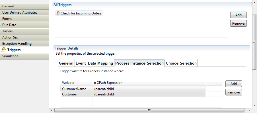
In this example, the trigger will fire if an incoming XML file contains the following data:
<order>
  ...
  <fromPartners>true</fromPartners>
  ...
</order>
The trigger will not fire if the following data come in:
<order>
  ...
  <fromPartners>false</fromPartners>
  ...
</order>
If you want a particular choice to be made only under certain conditions:
Select the Choice Selection sub-tab.
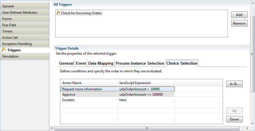
From the list, select the arrow for which you want to define a condition. Specify a JavaScript expression that defines the condition.
You can rearrange the order in which the conditions are evaluated by highlighting a condition and clicking the Up or Down button.
All conditions are checked in the sequence in which they appear in this dialog. The first matching condition is used and the process flow proceeds along this arrow.
Decide what is to happen if none of the conditions apply. From the If no expression is true, then list, you can either select an arrow or specify that the trigger is to wait for another event.
If you select an arrow, the process flow proceeds along the arrow to the next node. If you specify that the trigger is to wait for another event, the Activity Node remains active.
Say you wanted the vice president's approval of orders over $10,000. You would build a JavaScript expression like the following:
Figure 11.43 Defining Conditions for Arrows
Select the General sub-tab. Select the Enable check box to enable your trigger.
When a Trigger has been defined, the following symbol is added to this arrow connecting the Activity Node with another node:
Figure 11.44 Timer symbol
![]()