An operation component project is a container for managing the files that make up a single operation component.
This section explains how to create an operation component project.
Right-click on a category in the Operation Component Management view.
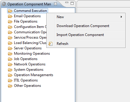
Select New and then Operation Component from the pop-up menu.
The New Operation Component Project dialog box will open.
Enter a name up to 128 characters for the name of the project in the Project Name field.
The project name must be unique on the workspace - it cannot be the same as another project on the workspace, for example an application project.
Enter a name up to 61 characters for the operation component in the Operation Component Name: field.
In the Operation Component ID: field, enter an ID to uniquely identify the operation component. In the field on the left, enter a prefix of up to five letters for the ID. In the field on the right, enter up to 55 characters (alphanumerics and underscores (_)).
Note
"SWRBA" cannot be used as a prefix for operation component IDs.
The specified operation component name is used as the default name prefix when the operation component node is placed in the process definition using the Process Definition Editor.
Use the Category combo-box to select a category for the operation component.
Enter a description of up to 4096 characters for the operation component in the Description field.
Click the Next button.
Note: The Finish button may also be clicked here.
Select the image file for the icon to be used in the Process Definition Editor or in the palette of Process Definition Editor.
Click the Browse button of the icon image (32x32) group and select the icon image file. (Optional)
The following icon is specified by default.
![]()
Point
Icons displayed in the Process Definition Editor are generated automatically by overlaying the basic images specified as icon images (32x32) and the other attribute images.
From the Modified Image Type combo-box, select the icon image type that will show the status.
The attribute image can be selected from the following 20 types.
Type | Image |
|---|---|
Execute, Start |
|
Re-execute |
|
Stop |
|
Pause |
|
Create, Add |
|
Delete |
|
Confirm, Monitor |
|
Search |
|
Get, Browse |
|
Set, Modify, Update |
|
Transfer |
|
Convert/Exchange |
|
Connect |
|
Disconnect |
|
Information/Details/Properties |
|
List/Table |
|
Restore |
|
Communication/Conversation |
|
| |
Repeat |
|
From the Modified Image Location combo-box, select the location for the overlay of the attribute image on the basic image.
The four locations that can be used for overlay for the basic image are the basic image's top right, top left, bottom left,bottom right,. If None is selected for Modified Image Type, the Modified Image Location combo box will be grayed out and cannot be selected.
In the same way, from the Icon Image(16x16) group specifyBasic Image, Modified Image Type and Modified Image Location. (Optional)
The following icon is specified by default.
![]()
In the Tooltip field, enter a simple description about the operation component. (Optional)
The description will be displayed as tooltip help when the cursor is aligned with the operation component node in the Process Definition Editor Palette.
Click the Next button.
Note: The Finish button may also be clicked here.
In the Input Output Data window, set the I/O information for executing the operation component.
When the Input Data tab is selected, this will change to the window used for setting the input information. When the Output Data tab is selected, the output information settings can be referenced.
When the Basic tab of Input Data is selected, the basic parameters can be set. When the Advanced tab of Input Data is selected, the extended parameters can be set.
To add/delete input information, click the Add and Delete buttons.
When the Select from List check box is selected, it will be possible to enter list format data.
When the Add button is clicked, the new item will be added to the end of the table control.
Item name: "NewItemText number", Value: "NewValue number" (If data type is INTEGER, it is "number"
Click the Finish button.