This section explains how to prepare to use the function for automatically configuring network devices.
Information
Automatic configuration of firewalls is not possible if they are not registered in a network pool.
Creating Model Definitions for Network Devices
Rulesets used for the function that automatically configures network devices are registered by network device model. Therefore, it is necessary to create model definitions for determining the models of network devices.
The created model definitions are enabled by registering the following XML definition file:
[Windows Manager]
Installation_folder\SVROR\Manager\etc\customize_data\network_device_model.xml
[Linux Manager]
/etc/opt/FJSVrcvmr/customize_data/network_device_model.xml
Newly-added models can be supported by editing the model definitions.
The network device model definitions provided with sample scripts for automatic configuration of network devices are automatically acquired, therefore it is not needed to enter them in the model definition file.
Information
When editing a model definition, check the sysObjectID of the network device using the snmpwalk command.
Example
snmpwalk -v 1 -c [SNMP_community_name] [IP_address] sysObjectID
If the information is available from the manual or vendor of the destination device, obtain it from there.
See
For details on model definitions for network devices, refer to "13.13 Network Device Model Definition" in the "Reference Guide (Command/XML) CE".
Note
Use the specified OID string as the SysObjectId element in the Model element to specify the model name of the network device.
The model definition file of network devices is searched from the start, and the first sysObjectID that matches will be used as the model name of the name attribute of the Model element.
When there is no matching OID string in the model definition file, the model name is not specified.
Creating a Folder for Registering Rulesets
The function for automatically configuring network devices is used by executing the scripts prepared by the infrastructure administrator for each network device.
When it is necessary to specify settings that differ according to the provided service, register these patterns as separate rules to manage them. This management is performed by the ruleset.
Create a folder for registering scripts, etc. for each ruleset.
There are two types of folders for registering rulesets; folders for L-Platform templates and folders for network resources.
Create the folders for registering rulesets for L-Platform templates with the following name:
[Windows Manager]
Installation_folder\SVROR\Manager\etc\scripts\vendor_name\unit_name or model_name\rulesets\ruleset_name\
[Linux Manager]
/etc/opt/FJSVrcvmr/scripts/vendor_name/unit_name or model_name/rulesets/ruleset_name/
Create the folders for registering rulesets for network resources with the following name:
[Windows Manager]
Installation_folder\SVROR\Manager\etc\scripts\network_resource\ruleset_name\
[Linux Manager]
/etc/opt/FJSVrcvmr/scripts/network_resource/ruleset_name/
Information
For "vendor_name", "unit_name", and "model_name", specify the "vendor name", "unit name", and "model name" of the target network device for script execution, respectively.
The "Vendor name", "unit name", and "model name" of a network device can be confirmed by checking the model definition (XML file) for that device.
For details on model definitions for network devices, refer to "13.13 Network Device Model Definition" in the "Reference Guide (Command/XML) CE".
Specify the folder name of "ruleset name" using up to 32 characters, including alphanumeric characters, underscores ("_"), and hyphens ("-"). This name should start with an alphabetical character.
Set a unique name for the folder name of "ruleset name", excluding the following folders in which sample scripts are registered.
[Windows Manager]
Installation_folder\SVROR\Manager\etc\scripts\
[Linux Manager]
/etc/opt/FJSVrcvmr/scripts/
Sample Scripts
Sample scripts to be used for automatic configuration of network devices are registered in the following folder when Resource Orchestrator is installed.
[Windows Manager]
Installation_folder\SVROR\Manager\etc\scripts\original\vendor_name\unit_name\rulesets\ruleset_name\
Installation_folder\SVROR\Manager\etc\scripts\original\network_resource\ruleset_name\
[Linux Manager]
/etc/opt/FJSVrcvmr/scripts/original/vendor_name/unit_name/rulesets/ruleset_name/
/etc/opt/FJSVrcvmr/scripts/original/network_resource/ruleset_name/
The following table lists the unit names supported by the sample scripts provided by Resource Orchestrator:
Vendor | Unit Name | Type | Setting Details |
|---|---|---|---|
Fujitsu | SR-X500 | L2 switch |
|
SR-X300 | |||
IPCOMEXSC | Firewall (*1) |
| |
IPCOMEXIN | |||
NSAppliance | |||
Cisco | Catalyst | L2 switch |
|
ASA5500 | Firewall (*1) |
|
*1: Configure Firewall rules for the VLAN interfaces of LAN ports to use as public LANs.
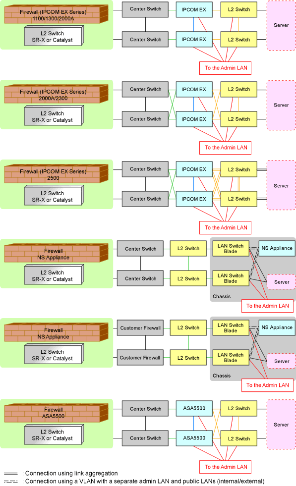
The default model configuration assumed by a sample script is given below:
Figure 9.19 Default Model Configuration for a Sample Script
Listed below are sample ruleset names provided by Resource Orchestrator:
For the systems that configure tagged VLANs on the LAN ports connected with firewalls and servers
For the systems that configure port VLANs on the LAN ports connected with firewalls and servers
For the systems that configure tagged VLAN networks
For the systems that configure untagged VLAN networks
n: Number of "2" or larger
For the systems that use IPCOMEX1100_SC/1300_SC/2000A_SC as an IPCOM EX SC series model for three-tier models
LAN Ports to be Used
For Public LANs (Center Switch Side)
LAN0.0
For Public LANs (L2 Switch Side)
LAN0.1
For the Admin LAN
LAN0.3
For Unit Synchronization
LAN0.2
For the systems that use IPCOMEX2000A_SC/2300_SC as an IPCOM EX SC series model for three-tier models
LAN Ports to be Used
For Public LANs (Center Switch Side)
bnd0: Redundant LAN Channels
LAN0.0
LAN1.0
For Public LANs (L2 Switch Side)
bnd1: Redundant LAN Channels
LAN0.1
LAN1.1
For the Admin LAN
LAN0.3
For Unit Synchronization
LAN1.3
For the systems that use IPCOMEX2500_SC as an IPCOM EX SC series model for three-tier models
LAN Ports to be Used
For Public LANs (Center Switch Side)
bnd0: Redundant LAN Channels
LAN0.0
LAN1.0
For Public LANs (L2 Switch Side)
bnd1: Redundant LAN Channels
LAN0.1 and LAN0.2
LAN1.1 and LAN1.2
Connection using Link aggregation
For the Admin LAN
LAN0.3
For Unit Synchronization
LAN1.3
For the systems that use IPCOMEX2000A_IN/2300_IN as an IPCOM EX IN series model for three-tier models
LAN Ports to be Used
For Public LANs (Center Switch Side)
bnd0: Redundant LAN Channels
LAN0.0
LAN1.0
For Public LANs (L2 Switch Side)
bnd1: Redundant LAN Channels
LAN0.1
LAN1.1
For the Admin LAN
LAN0.3
For Unit Synchronization
LAN1.3
For the systems that use IPCOMEX2500_IN as an IPCOM EX IN series model for three-tier models
LAN Ports to be Used
For Public LANs (Center Switch Side)
bnd0: Redundant LAN Channels
LAN0.0
LAN1.0
For Public LANs (L2 Switch Side)
bnd1: Redundant LAN Channels
LAN0.1 and LAN0.2
LAN1.1 and LAN1.2
Connection using Link aggregation
For the Admin LAN
LAN0.3
For Unit Synchronization
LAN1.3
For a system that uses NS Appliance with 3Tier model
LAN Ports to be Used
For Public LANs (Customer Firewall Side)
LAN0.0
For Public LANs (L2 Switch Side)
LAN0.1
For the Admin LAN
LAN0.3
For a system that uses NS Appliance with 3Tier model
LAN Ports to be Used
For Public LANs (Center Switch Side)
LAN0.0
For Public LANs (L2 Switch Side)
LAN0.1
For the Admin LAN
LAN0.3
For the systems that configure tagged VLANs on the LAN ports connected with firewalls and servers
For the systems that configure port VLANs on the LAN ports connected with firewalls and servers
For the systems that configure tagged VLAN networks
For the systems that configure untagged VLAN networks
n: Number of "2" or larger
For the systems that use ASA5510 as an ASA5500 series model for three-tier models
LAN Ports to be Used
For Public LANs (Center Switch Side)
redundant1: Redundant LAN Channels
ethernet0/0
ethernet0/1
For Public LANs (L2 Switch Side)
redundant2: Redundant LAN Channels
ethernet0/2
ethernet0/3
For the Admin LAN
management0/0
For the systems that use ASA5520/5540/5550 as an ASA5500 series model for three-tier models
LAN Ports to be Used
For Public LANs (Center Switch Side)
redundant1: Redundant LAN Channels
gigabitethernet0/0
gigabitethernet0/1
For Public LANs (L2 Switch Side)
redundant2: Redundant LAN Channels
gigabitethernet0/2
gigabitethernet0/3
For the Admin LAN
management0/0
For the systems that use ASA5580 as an ASA5500 series model for three-tier models
LAN Ports to be Used
For Public LANs (Center Switch Side)
redundant1: Redundant LAN Channels
gigabitethernet3/0
gigabitethernet3/1
For Public LANs (L2 Switch Side)
redundant2: Redundant LAN Channels
gigabitethernet3/2
gigabitethernet3/3
For the Admin LAN
management0/0
The following script lists are also provided as samples for each ruleset:
create.lst
Sample script list for additional configuration
modify.lst
Sample script list for configuration modification
delete.lst
Sample script list for configuration deletion
create_recovery.lst
Sample script list for recovery from errors detected during addition of settings
modify_recovery.lst
Sample script list for recovery from errors detected during modification of settings
connect.lst
Sample script list for configuration of interfaces adjacent to servers (only for L2 switches)
disconnect.lst
Sample script list for deletion of interfaces adjacent to servers (only for L2 switches)
connect_recovery.lst
Sample script list for recovery from errors detected during configuration of adjacent servers (only for L2 switches)
Note
The sample scripts provided by Resource Orchestrator may be added or deleted when the software is updated.
When using the sample scripts, confirm the directory on the admin server in which the sample scripts are registered beforehand.
Notes for automatic network device configuration using sample scripts.
For ruleset, It is required to register a folder created using the "Vendor" and "Unit Name described in "Table 9.8 Units for which Sample Scripts are Provided".
It is required to create following files according to the system configuration.
Parameter Files (for Scripts)
Please refer to "13.14 Parameter Files (for Scripts)" of "Reference Guide (Command/XML) CE" for information about parameter files.
Network Device Interface Configuration File
Please refer to "13.15 Network Device Interface Configuration File" of "Reference Guide (Command/XML) CE" for information about interface configuration of network devices.
Network device automatic configuration definition file
Script language or monitoring time of the script used for network device automatic configuration can be changed by setting the value in the following definition file beforehand.
[Windows Manager]
Installation_folder\SVROR\Manager\etc\customize_data
[Linux Manager]
/etc/opt/FJSVrcvmr/customize_data
unm_provisioning.rcxprop
Specify the script language when you want to use a language besides ruby.
Information
Ruby is used as the script language in sample scripts.
extension_<EXTENSION> = execution file path |
Specify the extension of the script language such as "rb" or "pl" for EXTENSION.
When there is no specification for the EXTENSION jruby is used.
Execution file path specifies the absolute path.
Example
extension_rb = /usr/bin/jruby
Specify the monitoring time when you want to change it to a value besides 300(s).
Information
In network device automatic configuration function, script execution time is monitored.
When monitoring time has passed since the beginning of the script execution, the processing of script is terminated.
EXECUTE_TIMEOUT=<monitoring time> |
Specify the monitoring time within the range of 1-7200(s).
When the specified value is non-numeric or is outside of the above mentioned range 300(s) is used.
Example
EXECUTE_TIMEOUT=600