Tagged VLAN allows multiple virtual networks on a single transfer path by assigning an identifier or a tag on the packet for disparate network. In order to build a Tagged VLAN environment, please ensure that you have switches/hubs that satisfy "IEEE 802.1Q" standard. The connection between switches/hubs that handles Tagged VLAN is called VLAN trunking. VLAN Trunking allows Tagged VLAN on each Switch/HUB to be handled on the same physical network cable.
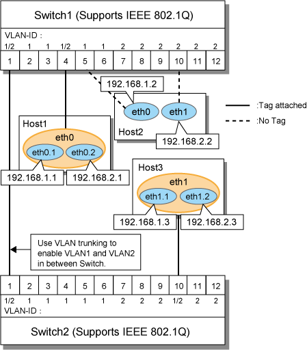
The figure below shows the network structure that uses Tagged VLAN.
Figure 2.29 Network structure using Tagged VLAN

In Figure 2.29 Network structure using Tagged VLAN, VLAN1(VLAN-ID:1) and VLAN2(VLAN-ID:2) are created on both Switch 1 and Switch 2, and port1 on both switches is used for VLAN Trunking.
A physical interface "eth0" on Host 1 has two VLAN interfaces "eth0.1" and "eth0.2", and is connected to port 4 on Switch 1 that belongs to both VLAN1 and VLAN2. Host 1 uses "eth0.1" and "eth0.2" to transmit tagged packets.
Similarly, a physical interface "eth1"on Host 3 has two VLAN interfaces "eth1.1" and "eth1.2", and is connected to port 10 on Switch 2 that belongs to both VLAN1 and VLAN2. Host 3 uses these VLAN interfaces to establish tagged packet communication.
Host 2 achieves data communications on both VLAN1 and VLAN2 by connecting a physical interface "eth0" to port 5 that belongs to VLAN1, and another physical interface "eth1" to port 10 that belongs to VLAN2.
Note
Ensure a switch/hub is configured to handle Tagged VLAN (IEEE 802.1Q).
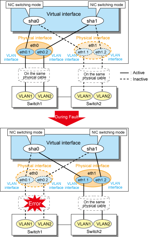
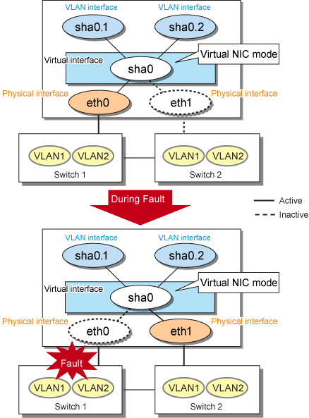
In Redundant Line Control Function, transfer paths can be multiplexed with tagged VLAN interfaces.
Figure 2.30 Using Tagged VLAN Interface architecture in NIC switching mode

Figure 2.31 Using Tagged VLAN Interface architecture in Virtual NIC mode

Point
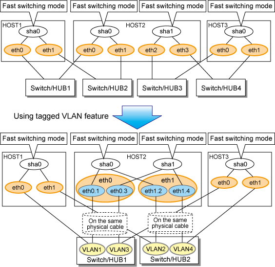
Even if switches/hubs or NICs come short, using tagged VLAN can provide sufficient number of transfer routes in various network architectures.
When building a server system as three-layered model, it is possible to implement transfer route multiplexing feature on an environment where number of Switch/HUB and NIC is constrained.
Figure 2.32 When Switch/HUB and NIC come short

See
For details on using Tagged VLAN for other modes, refer to "3.6.5 Transfer route multiplexing with Tagged VLAN interface".