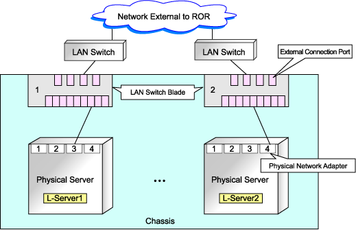
If network resources are connected when creating an L-Server, LAN switch blades will be registered automatically as the blade server that the L-Server will operate on.
If an image is specified, the IP address is configured.
Specify an IP address in a different subnet from the admin LAN.
For rack mount and tower servers, only connect network resources.
When creating a physical L-Server, the IP address cannot be automatically configured if specifying a Red Hat Enterprise Linux image.
Manually configure the IP address after the image has been deployed to the L-Server.
Physical Server (Blade Server) Configuration to Support Automation of Network Configuration in Resource Orchestrator
The physical server (blade server) configuration to support automation of network configuration (server blades, specification of uplink port for network resources, correspondence relations of numbers of LAN switch blades and physical network adapters, etc.) in Resource Orchestrator are shown in the following list. In this list, show the specifiable scope of physical network adapter numbers according to the server blade models, uplink port specifications and combination of LAN switch blades to use.
Server Blade | Specification of Uplink Port | LAN Switch Blade to Use | Physical Network Adapter Number |
|---|---|---|---|
BX920 S1 | CB1 and CB2, or no specification for uplink port | PG-SW111 | 1 - 4 |
PG-SW109 (*1) | 1, 2 | ||
CB3 and CB4 | PG-SW111 | 5 - 8 | |
PG-SW109 | 5, 6 | ||
BX924 S2 | CB1 and CB2, or no specification for uplink port | PG-SW111 | 1, 2 |
CB3 and CB4 | PG-SW111 | 3 - 6 | |
PG-SW109 | 3, 4 | ||
BX960 S1 | CB1 and CB2, or no specification for uplink port | PG-SW111 | 1, 2, 11, 12 |
CB3 and CB4 (*2) | PG-SW111 | 3 - 6 | |
PG-SW109 | 3, 4 |
*1: When installing a PG-SW109 on CB1 or CB2, set the transmission speed at the down link port of PG-SW109 to 1 Gbps. For details on how to configure the settings, refer to the corresponding hardware manual.
*2: Only configurations where LAN expansion cards are mounted in expansion slot 1 are supported.
Server Blade | Specification of Uplink Port | LAN Switch Blade to Use | Physical Network Adapter Number |
|---|---|---|---|
BX920 S2 | CB1 and CB2 (*1), or no specification for uplink port | PG-SW111 | 1 - 8 |
PG-SW109 (*2) | 1, 2, 5, 6 | ||
BX924 S2 | CB1 and CB2 (*1), or no specification for uplink port | PG-SW111 | 1 - 6 |
PG-SW109 | 1 - 4 |
*1: The same LAN switch blade model should be mounted in CB1 and CB2.
*2: When installing a PG-SW109 on CB1 or CB2, set the transmission speed at the down link port of PG-SW109 to 1 Gbps. For details on how to configure the settings, refer to the corresponding hardware manual.
Server Blade | Specification of Uplink Port | LAN Switch Blade to Use | Physical Network Adapter Number |
|---|---|---|---|
BX600 series servers | NET1 and NET2, or no specification for uplink port | PG-SW107 | 1 - 6 |
NET3 and NET4 | PG-SW104 | 7, 8 |
The NIC number of the L-Server the network resource above is allocated to is the number of the physical network adapter of the physical server.
When the LAN switch blade is in IBP mode, specify the NIC of the L-Server that network resources are allocated to as in the case when uplink ports have not been specified (internal network).
The physical server (blade server) configuration as described in the following configuration example when using a PRIMERGY BX900 S1 chassis is as shown below.
Server blades | BX920 S2 |
Specification of uplink port | CB1 and CB2 |
LAN switch blade to use | PG-SW112 |
Figure D.6 Physical Server (Blade Servers) Configuration (for PRIMERGY BX900 S1 Chassis)
