Problem
Cause
The cause may be one of the following:
Incorrect network route settings
Target network device is stopped or is not running correctly
Incorrect VLAN tag settings
No VLAN tag setting in the network device
Other
Action
Take action appropriate to the cause, as described below.
Incorrect network route settings
The ping monitor function may not work if any network adapters in the same system have the same network address.
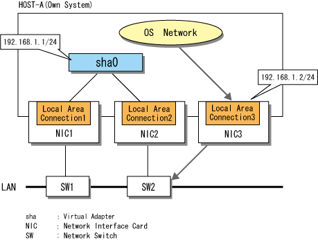
The figure below shows a network configuration that consists of a GLS virtual adapter and a physical adapter that is not a part of the GLS system.
The IP address of the GLS virtual adapter is 192.168.1.1/24, and the IP address of the physical adapter is 192.168.1.2/24.
Figure C.3 Ping Monitoring Fails Due to Incorrect Network Route Settings

In this example, the GLS virtual adapter (sha0) and the physical adapter (Local Area Connection 3) have the same network address. Because of this, pings are sent from the wrong route, and the GLS transmission path cannot be monitored.
The "route PRINT" command displays the routing table of the OS, as shown below.
> route PRINT
(Section Omitted)
Active Routes:
Network Destination        Netmask          Gateway       Interface  Metric
      192.168.1.0    255.255.255.0      192.168.1.2      192.168.1.2     XX
      192.168.1.0    255.255.255.0      192.168.1.1      192.168.1.1     XX
(Section Omitted)
===========================================================================
> |
Adapters that send IP packets such as pings are handled in descending order in the routing table of the OS. For this reason, in the example above, the ping packet sent for GLS monitoring purposes is handled as being sent from the non-GLS physical interface, and so the network that is intended to be monitored cannot be monitored.
Make sure to set different addresses for the GLS virtual adapter than for other network addresses.
Note that the problem of duplicate network addresses affects any network, regardless of whether or not GLS is used.
Target network device is stopped or is not running correctly
The communications device to be monitored may not respond to pinging. In such a case, check that the device is functioning correctly. If a network switch is set as the GLS ping monitor target, make sure that an IP address is set for the network switch.
Incorrect VLAN tag settings
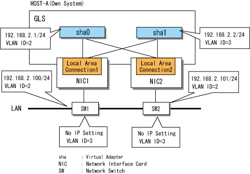
If VLAN tags are set for GLS virtual adapters, set an IP address with a different network address for each virtual adapter. The figure below shows a configuration in which incorrect communication is possible.
Figure C.4 Ping Monitoring Fails Due to Incorrect VLAN Tag Settings

[Ping Monitor Settings]
> hanetpoll print
 Polling Status         =  ON
         interval(idle) =   3( 60) sec
         times          =   5 times
 Adapter                         Fo  Target ip
+-------------------------------+---+------------------------------------------+
 Local Area Connection 1         YES 192.168.2.100
 Local Area Connection 2         YES 192.168.2.101
|
In a configuration such as in Figure C.4 with a routing table as follows, the GLS ping packet is sent from sha1 (VLAN=3). However, because no VLAN3 IP address is set for switches SW1 and SW2, ping monitoring fails.
> route PRINT |
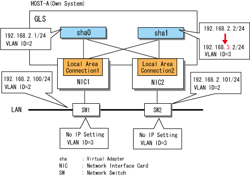
Set different network addresses for sha0 and sha1. In the example in Figure C.5, 192.168.3.2/24 is set as the IP address of sha1, which is different to the network address of sha0.
Figure C.5 Correct VLAN Tag Settings

No VLAN tag setting in the network device
If communication using VLAN tags is not possible, check that the VLAN tag settings of the ping monitor target switch and destination are correct.
Other
The GLS ping monitor function uses GLS virtual adapters. For this reason, whatever causes communication by virtual adapter to fail may also cause ping monitoring to fail. If the actions described above do not solve the problem, refer to "C.1.1 Cannot Communicate Using Virtual Adapters."