GLS virtual adapters can also use VLAN (IEEE802.1Q) tagging for communication.
By using VLAN tagging, you can build a system on multiple networks without being affected by hardware restrictions such as a limit on the number of internal NICs in the server.
Note
In order to use VLAN tagging, you must use network switches compatible with VLAN (IEEE802.1Q) tagging.
GLS data communication with VLAN tagging becomes available by using that function from either a physical adapter or from GLS. This allows you to set up multiple virtual networks on network devices connected to the same segment.
The diagram below illustrates the configuration of a system communicating by VLAN tagging.
Using the VLAN Tagging Function of a Physical Adapter
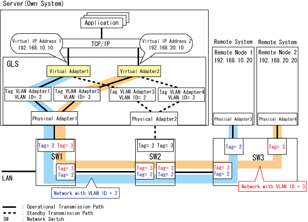
In the example below, redundant virtual adapters 1 and 2 are configured for VLAN tagging adapter pairs 1 & 2 and 3 & 4, which have been created in physical adapters 1 and 2, respectively. With VLAN tagging set for network switches 1 and 2, two networks are set up, using VLAN ID=2 and VLAN ID=3.
This configuration can be used if the NIC supports VLAN tagging and if VLAN tagging adapters can be created. For further details on VLAN tagging adapters, refer to the manual of each NIC.
Figure 2.8 Using the VLAN Tagging Function of a Physical Adapter (Sample Setup)

Virtual adapter 1 and virtual adapter 2 share a single physical line, but each adapter is assigned its own MAC address and IP address.
Virtual adapter 1 controls traffic on VLAN ID=2 and communicates with remote node 1.
Virtual adapter 2 controls traffic on VLAN ID=3 and communicates with remote node 2.
Using the VLAN Tagging Function of GLS
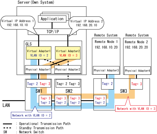
In the example below, redundant virtual adapters 1 and 2 are configured for physical adapters 1 and 2. With VLAN tagging set for network switches 1 and 2, two networks are set up, using VLAN ID=2 and VLAN ID=3.
This configuration has the following restrictions:
For Windows Server 2003 R2
When the NIC supports VLAN tagging, communication runs via unicast only, using static IPv4 addresses.
For Windows Server 2008 or later operating systems
When adapters (such as link aggregation of Intel PROSet) other than physical adapters are bundled, communication runs via unicast only, using static IPv4/IPv6 addresses.
For other types of communication, use a configuration that bundles the VLAN tagging adapters of the physical adapters.
Figure 2.9 Using the VLAN Tagging Function of GLS (Sample Setup)

Virtual adapter 1 and virtual adapter 2 share a single physical line, but each adapter is assigned its own MAC address and IP address.
Virtual adapter 1 controls traffic on VLAN ID=2 and communicates with remote node 1.
Virtual adapter 2 controls traffic on VLAN ID=3 and communicates with remote node 2.
Note
Do not use the VLAN tagging function of GLS when VLAN tagging adapters of physical adapters are bundled.