To register a network resource, specify a network pool when creating the network resource. For details, refer to "4.3.4 Network Resources".
The network environment, VM host, and physical server required to run Resource Orchestrator must satisfy the following prerequisites:
The configuration for the admin LAN and public LAN has been designed
The network environment for the admin LAN is configured
Note
When using an L-Server with the server type "Physical", the physical network adapter numbers available for the admin LAN are as below.
When not performing redundancy, "1" is available
When performing redundancy, "1" and "2" are available
The virtual switch to connect to the admin LAN has been designed and configured [VMware]
When using the VMware cluster function, the cluster configuration has been designed and configured [VMware]
For details on how to design and configure a network environment, refer to the following sections of the ServerView Resource Coordinator VE Setup Guide:
Defining the Network Environment
Configuring the Network Environment
Registering LAN Switches
Configuring VLANs on LAN Switch Blades
For details, refer to the "ServerView Resource Coordinator VE Setup Guide" and the VM host manual.
When using IBP
When using IBP, it is necessary to create IBP uplink set for the public LAN and the admin LAN in advance.
[Windows/Linux]
When the server type of an L-Server is "Physical", it is necessary to create an IBP uplink set for the public LAN and the admin LAN in advance, using VIOM.
Public LAN
Create a network resource with the same name as the created uplink set.
Admin LAN
Network resources for the admin LAN are created automatically.
Describe the name of the admin LAN uplink set in the uplink set definition file for the admin LAN.
When the definition file does not exist, define it as follows.
[Windows]
Installation_folder\Manager\etc\customize_data\vnetwork_ibp.rcxprop
external_admin_net_name=Admin_LAN_uplink_set_name |
[VMware/Hyper-V]
When the server type of the L-Server is "VM", connect the IBP uplink sets used for the public LAN and admin LAN to the VM host regardless of VIOM, after creating each IBP uplink set.
It is not necessary to combine the name of the uplink set and the name of the network resource.
If the NIC and network resources are connected when an L-Server is created, the following settings matching the network resource definition will be registered automatically for the VM host that the L-Server will operate on.
LAN switch blade (when using blade servers)
A tagged VLAN is configured on the internal ports.
Virtual switches, port groups
If the required network resources do not exist, they are automatically created. A redundant NIC configuration will be configured.
If it already exists, the virtual switch and port group are used.
VM guests
VM guests are connected to port groups.
If an image is specified, the IP address is automatically configured.
In environments using the clustering function of VM management software, in order to enable the migration of VM guests and operation using the HA function, settings for LAN switch blades, virtual switches, and port groups are performed automatically for all VM hosts comprising the cluster.
After creating an L-Server, if VM hosts are added to the cluster afterwards, Resource Orchestrator network settings are not performed automatically. Perform the same settings as the existing VM hosts in the cluster configuration for the LAN switch blades and virtual switches of the additional VM hosts.
The RC Console can be used for LAN switch blade configuration. Right-click the VM host in the server resource tree, and select [Change Setting]-[General] from the popup menu.
For details, refer to the information about configuring VLANs on LAN switch blades in the "ServerView Resource Coordinator VE Setup Guide".
Manually perform virtual switch and port group settings using VMware functions.
Advisory Notes About Automatic Network Configuration
Resource Orchestrator supports automation of network configuration for the following six patterns of VM host configuration.
Hardware | Number of LAN Switch Blades | Specification of Network Resource External Connection Ports | Number of Physical Network Adapter to Connect to Virtual Switch | |
|---|---|---|---|---|
a | PRIMERGY BX900 series servers | 2 | Select one from each of LAN switch blade 1 and 2 | Use 3 and 4 for teaming |
b | 4 | Select one from each of LAN switch blade 1 and 2 | Use 3 and 4 for teaming | |
c | 4 | Select one from each of LAN switch blade 3 and 4 | Use 5 and 6 for teaming | |
d | PRIMERGY BX600 series servers | 2 | Select one from each of LAN switch blade 1 and 2 | Use 3 and 4 for teaming |
e | 4 | Select one from each of LAN switch blade 1 and 2 | Use 3 and 4 for teaming | |
f | 4 | Select one from each of LAN switch blade 3 and 4 | Use 7 and 8 for teaming |
The numbers of physical network adapters given above can be checked on the details window of the LAN switch blade.
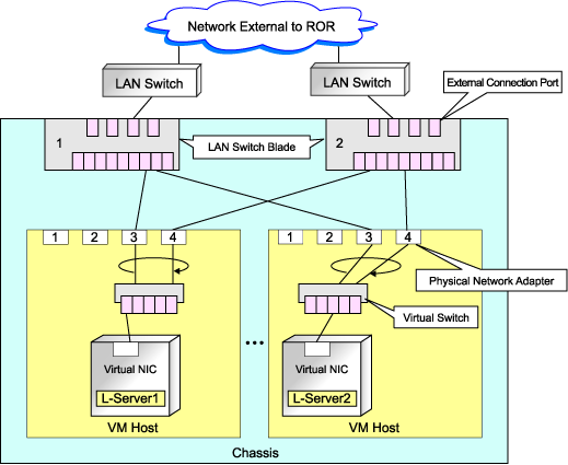
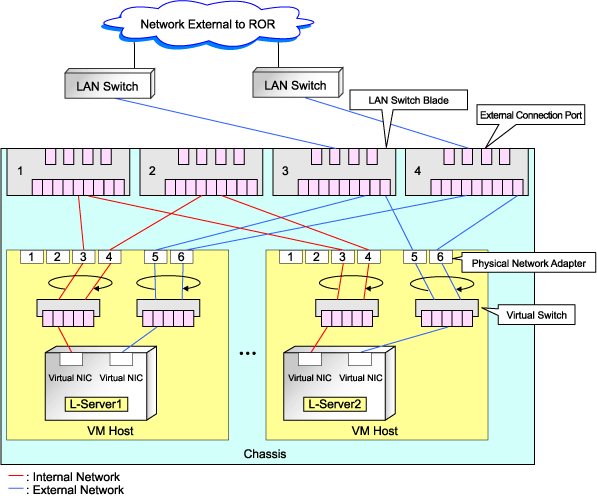
When external connection ports have not been specified (internal network) or the LAN switch blade is in IBP mode, the number 3 and number 4 physical network adapters will be used for teaming. (Enable 3 to perform redundancy)
When a virtual switch for use on the public LAN has been created in advance, or settings have been performed manually, it is necessary that the number of the physical network adapter the virtual switch is connected to matches the number in the details given above.
In rack mount server environments, only the function for connecting NICs of VM guests is provided for the port groups of virtual switches created in advance. Manually perform virtual switch and port group settings in advance. In this case, for the name of port groups using the same VLAN ID, it is necessary to use a common name on all VM hosts.
Advisory notes for automatic network configuration (VM host configuration) pattern A are as below.
Figure 4.1 Advisory Notes for Automatic Network Configuration (VM host Configuration) Pattern A
Advisory notes for automatic network configuration (VM host configuration) pattern C are as below.
Figure 4.2 Advisory Notes for Automatic Network Configuration (VM host Configuration) Pattern C
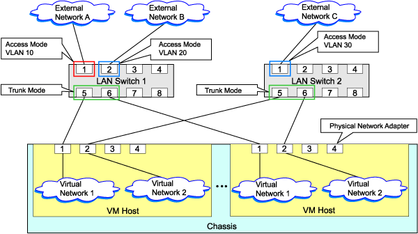
If the NIC and network resources are connected when an L-Server is created, a VLAN ID is automatically configured for the NIC of the VM guest, and connected to the virtual network.
In order to perform configuration automatically, it is necessary to use a different VLAN ID for each virtual network.
Additionally, the following settings must be performed in advance.
Create a virtual network
Create a virtual network with the same name (including upper and lower case characters) for all VM hosts comprising the cluster.
This enables migration of VM guests between VM hosts.
For details, refer to the procedure for addition or modification of virtual networks on hosts in the SCVMM help.
Configure the virtual network communication
Configure LAN switches to enable communication using the tagged VLAN between virtual networks using the same name.
When using blade servers, VLAN settings for LAN switch blades can be performed from the RC console.
Right-click the VM host in the server resource tree, and select [Change Setting]-[Network Information] from the popup menu.
For details, refer to the information regarding configuration of VLANs on LAN switch blades in the "ServerView Resource Coordinator VE Setup Guide".
Define the supported virtual network and VLAN ID
Supported virtual networks and VLAN IDs are defined in the following definition file of Resource Orchestrator:
Installation_folder\Manager\etc\customize_data\vnetwork_hyperv.rcxprop
For details on definition file format, refer to "File Format for Virtual Network Definitions".
An example of virtual NIC configuration and connection with virtual networks using network resources is given below:
Figure 4.3 Virtual NIC Configuration and Connection with Virtual Networks Using Network Resources [Hyper-V]
File Format for Virtual Network Definitions
Describe the virtual network definition file in one line as below:
"Virtual Network Name"=VLAN ID[,VLAN ID...] |
For the VLAN ID, 1 to 4094 can be specified. When specifying a sequence of numbers, use hyphen ("-") such as in "1-4094".
Example
"Network A"=10
"Network B"=21,22,23
"Network C"=100-200,300-400,500
Spaces before and after equal signs ("=") and commas (",") are ignored.
Describe the virtual network correctly, as the entry is case sensitive.
When using characters of languages other than English, use the following character codes:
Japanese: Shift-JIS
Other languages: UTF-8
When there are multiple lines with the same virtual network name, all specified lines are valid.
When the same VLAN ID is included in a line with a different virtual network name, the first occurrence in the file is valid and the lines after it are ignored.
Example
"Network D"=11
"Network D"=12 (*1)
"Network E"=11,15 (*2)
*1: Same as when "Network D"=11,12.
*2: 11 is ignored.
An error occurs during L-Server creation if the definition of the VLAN ID of the network resource connected to the NIC cannot be found.
If network resources are connected when creating an L-Server, LAN switch blades will be registered automatically as the physical server that the L-Server will operate on.
If an image is specified, the IP address is configured.
However, when a Red Hat Enterprise Linux image is specified when creating an L-Server with server type "Physical", the IP address will not be configured automatically.
Manually configure the IP address after the image has been deployed to the L-Server.
Network resources cannot be connected, as NIC1 is always used for the admin LAN.
Advisory Notes About Automatic Network Configuration
Resource Orchestrator supports automation of network configuration for the following six patterns of physical server configuration.
Hardware | Number of LAN Switch Blades | Specification of Network Resource External Connection Ports | Physical Network Adapter Number | |
|---|---|---|---|---|
a | PRIMERGY BX900 series servers | 2 | Select one from each of LAN switch blade 1 and 2 | 3 or 4 |
b | 4 | Select one from each of LAN switch blade 1 and 2 | 3 or 4 | |
c | 4 | Select one from each of LAN switch blade 3 and 4 | 5 or 6 | |
d | PRIMERGY BX600 series servers | 2 | Select one from each of LAN switch blade 1 and 2 | 3 or 4 |
e | 4 | Select one from each of LAN switch blade 1 and 2 | 3 or 4 | |
f | 4 | Select one from each of LAN switch blade 3 and 4 | 7 or 8 |
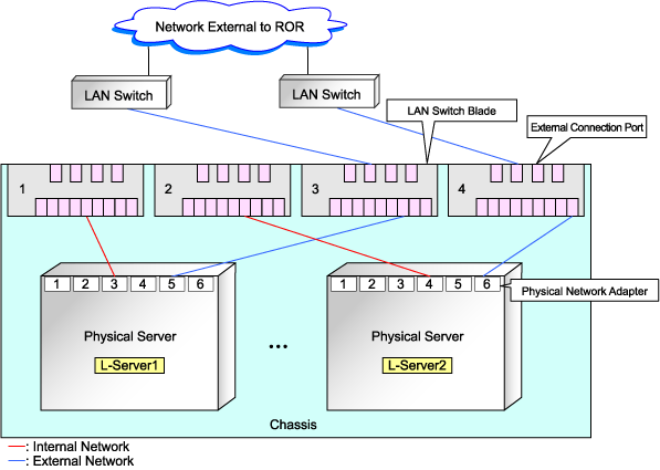
The NIC number of the L-Server the network resource above is assigned to is the number of the physical network adapter of the physical server.
The numbers of physical network adapters can be checked on the details window of the LAN switch blade.
When external connection ports have not been specified (internal network) or the LAN switch blade is in IBP mode, specify 3 or 4 for the L-Server NIC assigning the network resource.
Advisory notes for automatic network configuration (Physical server configuration) pattern A are as below.
Figure 4.4 Advisory Notes for Automatic Network Configuration (Physical Server Configuration) Pattern A
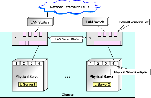
Advisory notes for automatic network configuration (Physical server configuration) pattern C are as below.
Figure 4.5 Advisory Notes for Automatic Network Configuration (Physical Server Configuration) Pattern C
