
| PRIMECLUSTER Global Link Services Configuration and Administration Guide: Redundant Line Control Function 4.1 (for Solaris(TM) Operating System) |
Contents
Index
 
|
| Chapter 5 GLS operation on cluster systems | > 5.1 Outline of Cluster System Support | > 5.1.3 Cascade | > 5.1.3.1 Startup |
There are three types of IP takeover feature in NIC switching mode. For detail, refer to "5.1.1.1.2 NIC switching mode".
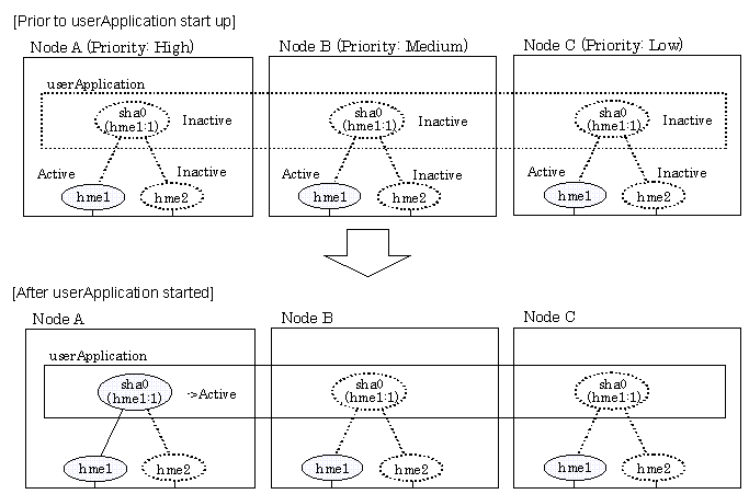
The physical interface (hme1) for each node becomes active when the redundant control function starts up for logical IP takeover. Once the userApplication starts up, takeover virtual interface (hme1:1) then becomes active on the operating node which has higher priority.
Figure 5.21 illustrates start-up behavior of logical IP takeover.

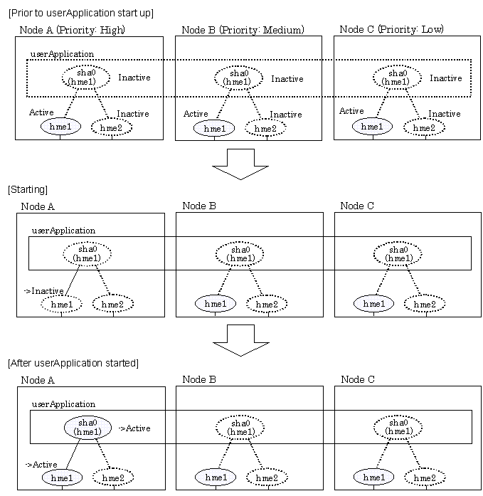
The physical interface (hme1) for each node becomes active when the redundant control function starts up for the physical IP takeover I. Once the userApplication starts up, it activates the physical interface (hme1) by allocating the takeover IP address to the physical interface (hme1) on the operating node, which has a higher priority. During this process, the physical interface (hme1) on the standby node maintains its state.
Figure 5.22 illustrates start-up behavior of the physical IP takeover I.

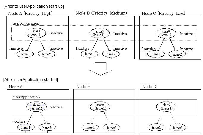
The physical interface (hme1) for each node stays to be inactive when the redundant control function starts up for the physical IP takeover II. Once the userApplication starts up, it activates the physical interface (hme1) by allocating the takeover IP address to the physical interface (hme1) on the operating node, which has a higher priority. While this process takes place, the physical interface on the standby node remains inactive.
Figure 5.23 illustrates start-up behavior of physical IP takeover II

Contents
Index
 
|