
| PRIMECLUSTER Global Link Services Configuration and Administration Guide: Redundant Line Control Function 4.1 (for Solaris(TM) Operating System) |
Contents
Index
 
|
| Chapter 2 Feature description | > 2.3 Other functions |
Tagged VLAN allows multiple virtual networks on a single transfer path by assigning an identifier or a tag on the packet for disparate network. In order to build a Tagged VLAN environment, please ensure that you have NICs and switches/hubs that satisfy "IEEE802.1Q" standard. The connection between switches/hubs that handles Tagged VLAN is called VLAN trunking. VLAN Trunking allows Tagged VLAN on each Switch/HUB to be handled on the same physical network cable.
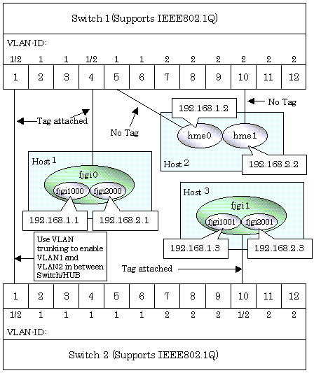
The figure below shows the network structure that uses Tagged VLAN

In Figure 2.47, VLAN1(VLAN-ID:1) and VLAN2(VLAN-ID:2) are created on both Switch 1 and Switch 2, and port1 on both switches is used for VLAN Trunking.
A physical interface "fjgi0" on Host 1 has two VLAN interfaces "figi1000" and "fjgi2000", and is connected to port 4 on Switch 1 that belongs to both VLAN1 and VLAN2. Host 1 uses "fjgi1000" and "fjgi2000" to transmit tagged frames.
Similarly, a physical interface "fjgi1"on Host 3 has two VLAN interfaces "fjgi1001" and "fjgi2001", and is connected to port 10 on Switch 2 that belongs to both VLAN1 and VLAN2. Host 3 uses these VLAN interfaces to establish tagged frame communication.
Host 2 achieves data communications on both VLAN1 and VLAN2 by connecting a physical interface "hme0" to port 5 that belongs to VLAN1, and another physical interface "hme1" to port 10 that belongs to VLAN2.

 2.3.5.1 Redundant Line Control function using Tagged VLAN interface
Contents
Index
 
|