
| PRIMECLUSTER Global Link Services Configuration and Administration Guide: Redundant Line Control Function 4.1 (for Solaris(TM) Operating System) |
Contents
Index
 
|
| Chapter 2 Feature description | > 2.1 Overview of Functions |
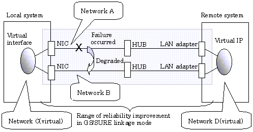
In this mode, each of multiple NICs (Network Interface Cards) is connected to a different network. Then, all the NICs are activated and used concurrently. Outgoing packets are assigned to the lines in units of TCP connections.
Thus, different lines are used for different connections for communication. If a failure occurs on one of the lines, communication can continue using another line, offering improved line reliability.
As with Fast switching mode and RIP mode, a virtual interface is created and then a virtual network is allocated to it. A TCP/IP application can carry out communication with the remote system, irrespective of the physical network redundant configuration, by using a virtual IP address set in this virtual interface as its own local system IP address.


If the GS/SURE linkage communication function is to be used, the systems among which communication is to be carried out must be connected on the same network. Connecting systems on different networks is not allowed.
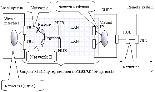
If the TCP relay function is to be used, the local system and the remote system on a different network can communicate with each other via SURE.
Lines are used in units of TCP connections for communication. If a failure occurs on a line, processing can continue on another line that is normal. Since all the redundant lines are activated for use, each of the lines can be directly used for a different purpose, enabling efficient use of resources.
GS/SURE linkage mode is appropriate, for example, for communication in a multi-server environment where GS/SURE and GP are mixed or for IP-based reconstruction of network infrastructures of a legacy system.
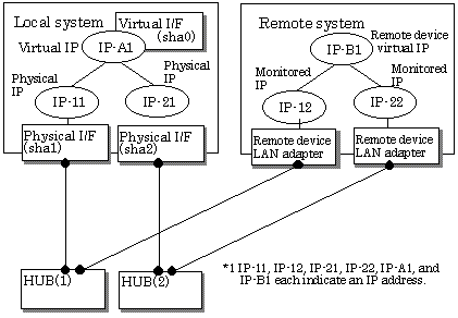
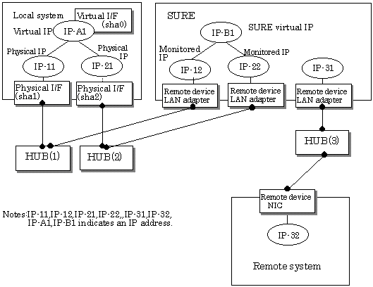
Figures 2.19 and 2.20 show a system configuration of GS/SURE linkage mode (GS/SURE communication function) and of GS/SURE linkage mode (TCP relay function), respectively.


The following explains each component and its meaning:
Indicates a physical interface (such as sha1 and sha2) of the duplicated NIC.
Indicates an IP address to be attached to a physical interface. This IP address is always active. Use the IP address to manage a node by using the cluster operation management view, etc. IPv4 address can be used for a physical interface.
Indicates a virtual interface (such as sha0) used to handle duplicated NICs as one NIC.
Indicates a local IP address to be attached to a virtual interface for communication with remote devices. This IP address is activated on the active node. In cluster operation, the IP address is taken over by the standby node when clusters are switched. IPv4 address can be used for a physical interface.
Indicates a NIC of the relay and remote devices.
Indicates an IP set to the NIC of the remote device. This IP address is monitored. IPv4 address can be used for a physical interface.
Indicates a virtual IP of the remote device with which communication should be carried out. IPv4 address can be used for a physical interface.
 2.1.4.1 Fault monitoring function
 2.1.4.2 Switching function
 2.1.4.3 Connectable remote host
 2.1.4.4 Available applications
 2.1.4.5 Notes
Contents
Index
 
|