

| PRIMECLUSTER Global Link Services Configuration and Administration Guide: Redundant Line Control Function 4.1 (for Solaris(TM) Operating System) |
|
Contents
Index
|
| Chapter 1 Overview |
Redundant Line Control function consists of the following components:
|
Network device |
PRIMEPOWER, GP7000F Series |
|
|
NIC (Network Interface Cards) |
The following Fujitsu adapters or cards can be used: *1: InfiniBand is a trademark and/or service mark of the InfiniBand Trade Association. |
|
|
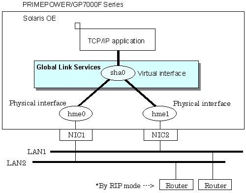
Router (RIP mode) |
The following router is recommended: |
|
|
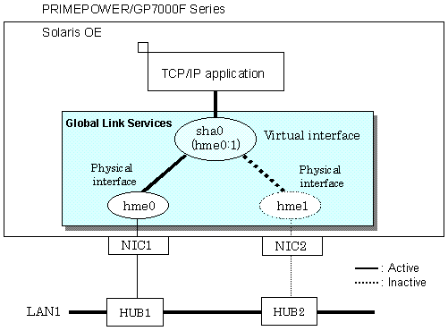
HUB (NIC switching mode) |
IP address information must be configured for HUB, e.g. HUB with SNMP agent |
|
|
Operating system (OS) |
- Solaris 8 (32-bit and 64-bit modes) |
|
|
Interfaces |
Physical interface |
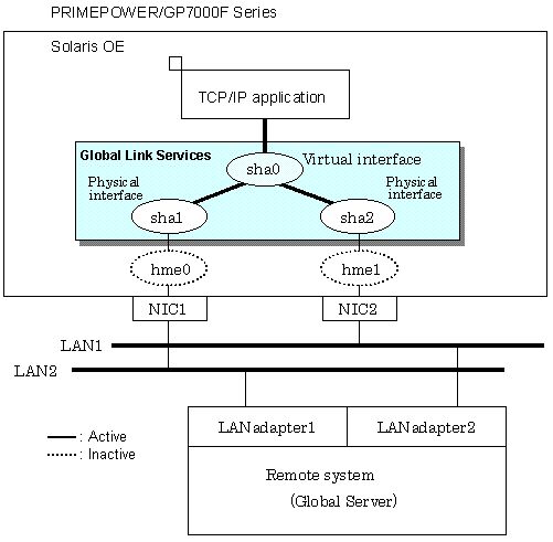
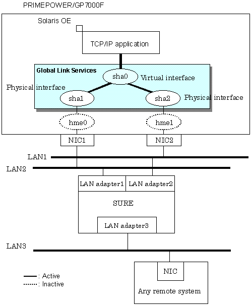
Generated by each NIC. The interface name is determined by the NIC type (e.g. hmeX and qfeX). In GS/SURE linkage mode, physical interfaces are generated through redundant line control. The interface name is shaX. |
|
Tagged VLAN interface |
Logical interface generated by NIC that supports a tagged VLAN (IEEE802.1Q). The interface name varies depending on NIC type (e.g. ce1000, fjgi2001) |
|
|
Virtual interface |
Generated through redundant line control (e.g. sha0 and sha1). Network applications can communicate using a virtual IP address assigned to the virtual interface. In NIC switching, the virtual interface name is used technically although no virtual interface is generated. A logical IP is allocated to the actual network so that the network applications enable communication through the logical IP address. |
|
|
Network number |
Fast switching mode, RIP mode, and GS/SURE linkage mode |
A different network number is assigned to each physical interface and a virtual interface. |
|
NIC switching mode |
Only one number is assigned to each network. No virtual interface is generated |
|
|
IP address |
Fast switching mode |
An IP address must be allocated to each physical interface and a virtual interface. If there are two or more virtual interfaces, an IP address will be allocated to each virtual interface. Both IPv4 address and IPv6 address can be used. |
|
NIC switching mode |
An IP address must be allocated to each logical interface. If there are two or more logical interfaces, an IP address will be allocated to each logical interface. Both IPv4 address and IPv6 address can be used. |
|
|
RIP mode, and GS/SURE linkage mode |
An IP address must be allocated to each physical interface and a virtual interface. If there are two or more virtual interfaces, an IP address will be allocated to each virtual interface. Only IPv4 can be used. |
|
|
Contents
Index
|