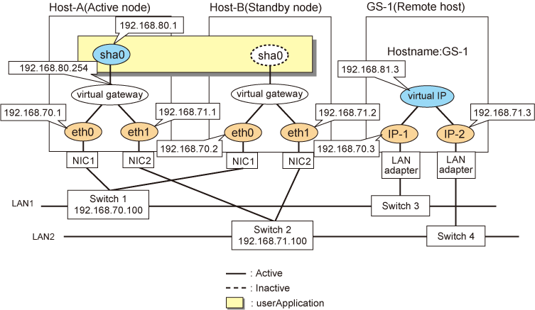
This section describes an example configuration procedure of the network shown in the diagram below.
For the network configuration other than GLS, refer to "3.2.2 Network configuration".
For the GS configuration, refer to GS manual.
For configuring the cluster system, refer to the Cluster system manual.
In this section, description of private LAN is omitted.
The dotted line indicates that the interface is inactive.

[HOST-A]
1) Setting up the system
1-1) Define IP addresses and hostnames in the /etc/hosts file.
192.168.70.1 host11 # HOST-A Physical IP 192.168.71.1 host12 # HOST-A Physical IP 192.168.70.2 host21 # HOST-B Physical IP 192.168.71.2 host22 # HOST-B Physical IP 192.168.80.1 hosta # HOST-A/B Virtual IP(Takeover virtual IP) 192.168.80.254 virgw # Virtual gateway 192.168.70.3 gs11 # GS-1 Physical IP(IP-1) 192.168.71.3 gs12 # GS-1 Physical IP(IP-2) 192.168.81.3 gsa # GS-1 Virtual IP |
For RHEL8
1-2) Configure the /etc/sysconfig/network-scripts/ifcfg-ethX (X is 0, 1) file as follows.
Contents of /etc/sysconfig/network-scripts/ifcfg-eth0
TYPE=Ethernet BOOTPROTO=none IPADDR=192.168.70.1 PREFIX=24 DEVICE=eth0 ONBOOT=yes |
Contents of /etc/sysconfig/network-scripts/ifcfg-eth1
TYPE=Ethernet BOOTPROTO=none IPADDR=192.168.71.1 PREFIX=24 DEVICE=eth1 ONBOOT=yes |
1-3) Set the static route information of the virtual gateway for the remote host's virtual IP address in the /etc/sysconfig/network-scripts/route-"interface name" file.
Contents of /etc/sysconfig/network-scripts/route-sha0
GATEWAY0=192.168.80.254 # Virtual gateway NETMASK0=255.255.255.255 # Subnet mask ADDRESS0=192.168.81.3 # GS-1 Virtual IP |
For RHEL9
1-2) Set the IP address defined above with the "nmcli connection modify" command.
Configuration of eth0
Set the following parameters with the "nmcli connection modify" command.
ipv4.method: "manual" ipv4.addresses: "192.168.70.1/24" connection.autoconnect: "yes" |
Configuration of eth1
Set the following parameters with the "nmcli connection modify" command.
ipv4.method: "manual" ipv4.addresses: "192.168.71.1/24" connection.autoconnect: "yes" |
After setting, verify that the following parameters are set for ethX with the nmcli connection show command.
connection.type: "802-3-ethernet" connection.id: "ethX" connection.interface-name: "ethX" |
2) Reflecting system setting
Run the following command and reload the connection profile. After reloading the profile, verify eth0 and eth1 are enabled using the ip command.
/usr/bin/nmcli connection reload
/usr/bin/nmcli connection up eth0
/usr/bin/nmcli connection up eth1
3) Setting a subnet mask
/opt/FJSVhanet/usr/sbin/hanetmask create -i 192.168.80.0 -m 255.255.255.0
4) Creating a virtual interface
/opt/FJSVhanet/usr/sbin/hanetconfig create -n sha0 -m c -i 192.168.80.1 -t eth0,eth1
5) Setting the Communication target monitoring function
Setting the Remote host monitoring information:
/opt/FJSVhanet/usr/sbin/hanetobserv create -n GS-1 -i 192.168.81.3 -t 192.168.70.3,192.168.71.3
Setting the destination cluster node monitoring information and the switches monitoring information:
/opt/FJSVhanet/usr/sbin/hanetobserv create -n HOST-B -i 192.168.80.1 -t 192.168.70.2,192.168.71.2,192.168.70.100,192.168.71.100
Note
When you set the destination cluster node monitoring information and the switches monitoring information, be sure to specify the takeover IP address with the "-i" option.
6) Setting a virtual gateway
/opt/FJSVhanet/usr/sbin/hanetgw create -n sha0 -g 192.168.80.254
7) Creating a takeover virtual interface
/opt/FJSVhanet/usr/sbin/hanethvrsc create -n sha0
8) Reboot
Run the following command to reboot the system.
/sbin/shutdown -r now
[HOST-B]
1) Setting up the system
1-1) Define IP addresses and hostnames in the /etc/hosts file. Defined information is the same as for HOST-A.
For RHEL8
1-2) Configure the /etc/sysconfig/network-scripts/ifcfg-ethX (X is 0, 1) file as follows.
Contents of /etc/sysconfig/network-scripts/ifcfg-eth0
TYPE=Ethernet BOOTPROTO=none IPADDR=192.168.70.2 PREFIX=24 DEVICE=eth0 ONBOOT=yes |
Contents of /etc/sysconfig/network-scripts/ifcfg-eth1
TYPE=Ethernet BOOTPROTO=none IPADDR=192.168.71.2 PREFIX=24 DEVICE=eth1 ONBOOT=yes |
1-3) Set the static route information of the virtual gateway for the remote host's virtual IP address in the /etc/sysconfig/network-scripts/route-"interface name" file. The information is set in the same way as for HOST-A.
For RHEL9
1-2) Set the IP address defined above with the "nmcli connection modify" command.
Configuration of eth0
Set the following parameters with the "nmcli connection modify" command.
ipv4.method: "manual" ipv4.addresses: "192.168.70.2/24" connection.autoconnect: "yes" |
Configuration of eth1
Set the following parameters with the "nmcli connection modify" command.
ipv4.method: "manual" ipv4.addresses: "192.168.71.2/24" connection.autoconnect: "yes" |
After setting, verify that the following parameters are set for ethX with the nmcli connection show command.
connection.type: "802-3-ethernet" connection.id: "ethX" connection.interface-name: "ethX" |
2) Reflecting system setting
Run the following command and reload the connection profile. After reloading the profile, verify eth0 and eth1 are enabled using the ip command.
/usr/bin/nmcli connection reload
/usr/bin/nmcli connection up eth0
/usr/bin/nmcli connection up eth1
3) Setting a subnet mask
/opt/FJSVhanet/usr/sbin/hanetmask create -i 192.168.80.0 -m 255.255.255.0
4) Creating a virtual interface
/opt/FJSVhanet/usr/sbin/hanetconfig create -n sha0 -m c -i 192.168.80.1 -t eth0,eth1
5) Setting the Communication target monitoring function
Setting the Remote host monitoring information:
/opt/FJSVhanet/usr/sbin/hanetobserv create -n GS-1 -i 192.168.81.3 -t 192.168.70.3,192.168.71.3
Setting the destination cluster node monitoring information and the switches monitoring information:
/opt/FJSVhanet/usr/sbin/hanetobserv create -n HOST-A -i 192.168.80.1 -t 192.168.70.1,192.168.71.1,192.168.70.100,192.168.71.100
Note
When you set the destination cluster node monitoring information and the switches monitoring information, be sure to specify the takeover IP address with the "-i" option.
6) Setting a virtual gateway
/opt/FJSVhanet/usr/sbin/hanetgw create -n sha0 -g 192.168.80.254
7) Creating a takeover virtual interface
/opt/FJSVhanet/usr/sbin/hanethvrsc create -n sha0
8) Reboot
Run the following command to reboot the system.
/sbin/shutdown -r now
[Configuration by RMS Wizard]
After completing the procedure 7) for HOST-A and HOST-B, use the RMS Wizard to set up the cluster environment.
Select the SysNode for HOST-A and HOST-B when creating GLS resources, and then register the created GLS resources with the cluster applications.
When registering the GLS resources with the cluster applications, select the SysNode for HOST-A and HOST-B in order of the operation node and the standby node, and then register the takeover IP address "192.168.80.1".
After completing the configuration, start the userApplication to activate the takeover virtual interface on the operation node.
[GS-1]
Set the information for HOST-A's physical IP address and virtual IP address. For information on how to do this, see the GS manual.