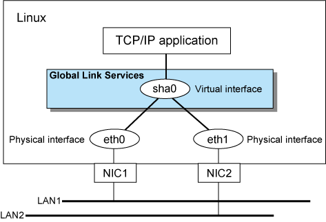
Figure 1.6 Fast switching mode

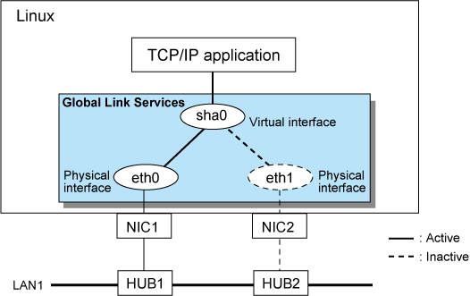
Figure 1.7 NIC switching mode

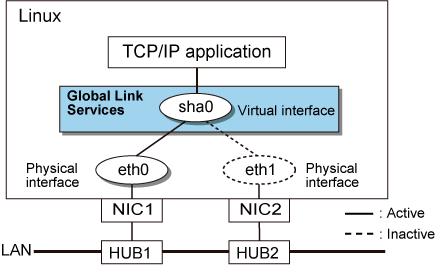
Figure 1.8 Virtual NIC mode

Figure 1.9 GS linkage mode

Redundant Line Control function consists of the following components:
Component | Description | |
|---|---|---|
Main unit |
| |
NIC (Network Interface Cards) | The following Fujitsu cards can be used:
| |
Switch/HUB (NIC switching mode, Virtual NIC mode) | IP address information must be configured for switch/HUB, e.g. switch/HUB with SNMP agent | |
Operating system (OS) | For details about the operating system supported by the redundant line control function, see the Installation Guide. | |
Interfaces | Physical interface | Generated by each NIC. |
Tagged VLAN interface | Interface (e.g. eth0.2, eth1.3) that is generated through tagged VLAN (IEEE 802.1Q). In Virtual NIC mode, a tagged VLAN interface (e.g. sha0.X) is generated on a virtual interface for redundant communication of a tagged VLAN. | |
Virtual interface | Generated through redundant line control (e.g. sha0 and sha1). | |
IP address | Fast switching mode | An IP address must be allocated to each physical interface and a virtual interface. If there are two or more virtual interfaces, an IP address will be allocated to each virtual interface. Both IPv4 address and IPv6 address can be used. |
NIC switching mode | An IP address must be allocated to each logical interface. If there are two or more logical interfaces, an IP address will be allocated to each logical interface. Both IPv4 address and IPv6 address can be used. | |
Virtual NIC mode | Both IPv4 address and IPv6 address can be used as an address form. | |
GS linkage mode | An IP address must be allocated to each physical interface and a virtual interface. If there are two or more virtual interfaces, an IP address will be allocated to each virtual interface. Only IPv4 can be used. | |