This section outlines the cluster system configurations that are possible when a cluster configuration is used for the entire Systemwalker Operation Manager server system.
1:1 active/standby configuration
In this configuration, the way that jobs are taken over by the standby node differs in the non multi-subsystem operation and the multi-subsystem operation.
Non multi-subsystem operation
In the following figure, Node 1 is operating as the active node, and Node 2 is operating as the standby node.
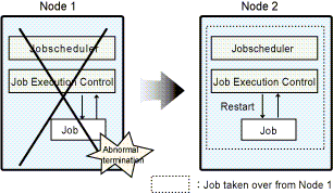
If error occurs with Node 1, jobs are taken over by Node 2.
Multi-subsystem operation
This operational configuration is available in the following cluster systems:
PRIMECLUSTER for Solaris version
PRIMECLUSTER for Linux version
MC/ServiceGuard
HACMP
In the following figure, Node 1 is operating as the active node, and Node 2 is operating as the standby node. This figure shows an example where the multi-subsystem operation is implemented in Subsystem 0 and Subsystem 1, and error occurs with Node 1. If error occurs with Node 1, all the jobs in Subsystem 0 and Subsystem 1 are taken over by the standby node.
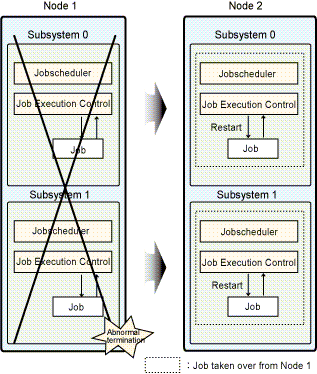
If error occurs with Subsystem 1 on Node 1, the jobs in Subsystem 0 are also taken over by Node 2.
The configurations -- the non multi-subsystem operation in 1:1 active/standby configuration and the multi-subsystem operation in 1:1 active/standby configuration--are each referred to as the follow:
1:1 active/standby configuration (without subsystems)
1:1 active/standby configuration (with subsystems)
The term "1:1 active/standby configuration" includes 1:1 active/standby configurations without subsystems, active/standby configurations with subsystems, and active/standby configurations with subsystems and partial cluster operation.
N:1 active/standby configuration
This operational configuration is available in the following cluster systems:
PRIMECLUSTER for Solaris version
PRIMECLUSTER for Linux version
Oracle Solaris Cluster
MC/ServiceGuard
In the following figure, Node 1 and Node 3 are running as active nodes, and Node 2 is running as standby node. In this example, if error occurs with Node 1, jobs on Node 1 are taken over by Node 2. Similarly, jobs on Node 3 will be taken over by Node 2 if error occurs with Node 3.
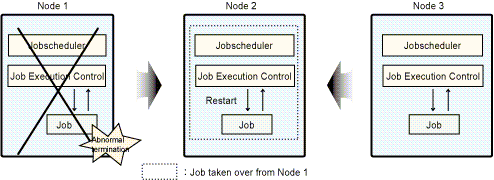
If error occurs with either Node 1 or Node 3, jobs are taken over by Node 2. If errors occur with more than one node, then only jobs from the node where error occurred first will be taken over by the standby node. Jobs from the second failed node will not be taken over.
Dual node mutual standby configuration
In the following figure, Node 1 and Node 2 are on standby for one another while each node executes its own jobs. In this example, if error occurs with Node 1, jobs on Node 1 are taken over by Node 2. Similarly, jobs on Node 2 will be taken over by Node 1 if error occurs with Node 2.
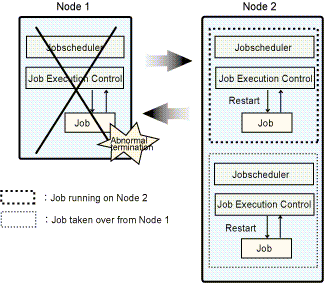
Cascading configuration
This configuration is available only in PRIMECLUSTER.
In the following figure, Node 2 and Node 3 are on standby while jobs are executed on Node 1.
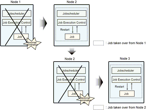
If error occurs with Node 1, jobs will be taken over by Node 2. If error then occurs with Node 2, jobs will be taken over by Node 3.